Page 56 of 58
9.3 Detector Module Replacement
Inspect the optical block where the detector module is to be attached: look to see that there is no dirt or
damage around the three small contact pins located above the large hole in the optics block. If any dirt
is evident, remove it with a soft brush but avoid blowing it into the optical block.
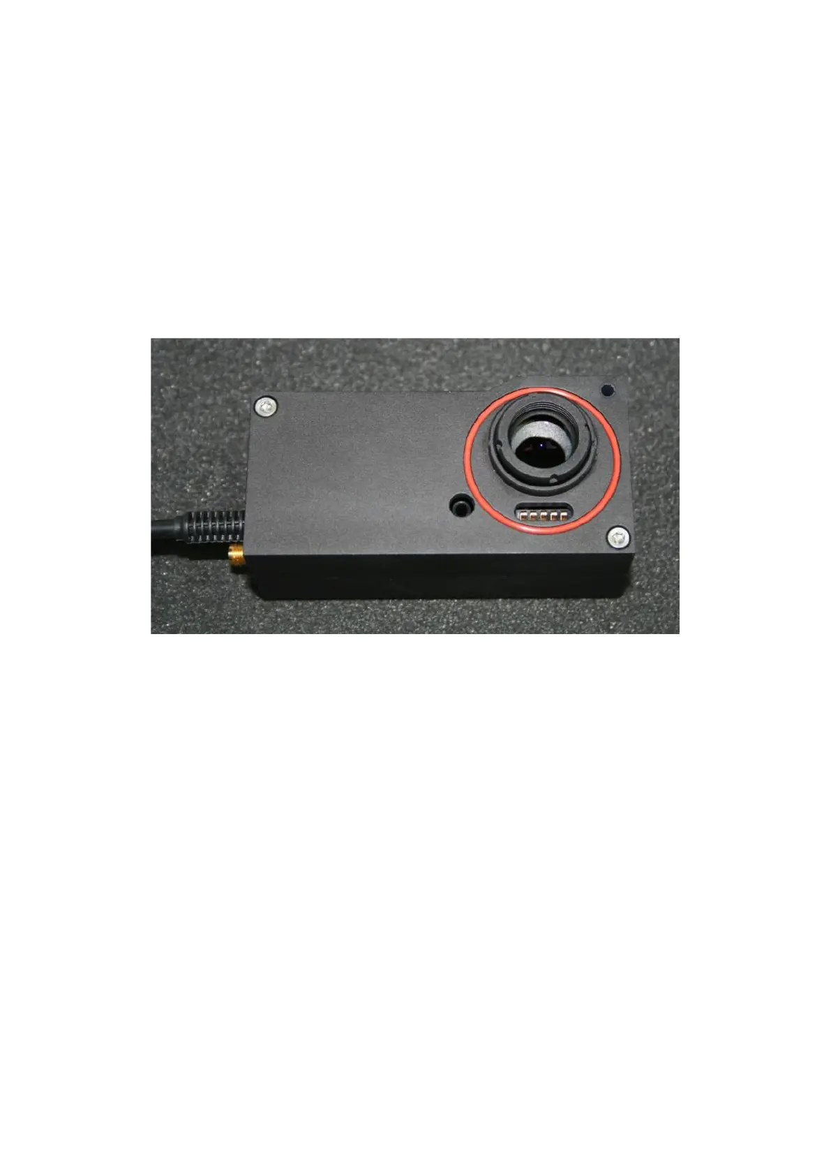
Front view of a standard PMT module showing lens, O-ring and safety contacts.
Inspect the front of the PMT module before assembling it:
o The lens should be clean, free of dust and finger-prints. Refer to cleaning advice in the
appendix if this is not the case.
o The O-ring should be present in its groove (it may be red or black in colour), and it should be
smooth and clean. This O-ring acts as a stray-light shield.
o Check that the five small contact springs lie centrally within the slot, that they are un-distorted
and free of dirt or debris.
Lift the module and insert the two long M3 bolts into the holes.
Gently offer the PMT module up to the optical block so that the lens and holder enters the hole in the
optical block, and keep the module as level as possible. When the module is fully home against the
optical block, gently tighten the two M3 screws, starting with the bolt nearest the middle of the module,
and following with the bolt in the corner of the module. Do not tighten either bolt fully yet.