Page 10 of 58
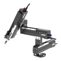
One substage support bracket (factory fitted)
incorporating X,Y adjustment controls.
Two M5 X 20 mm bolts for attaching to the
SliceScope
One kit of Allen keys, including one 4 mm ball-
ended driver for the main attachment bolts.
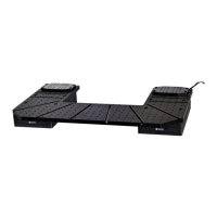
Two transit caps (upper and lower)
One U-MF2 Olympus filter cube (un-populated)
One 1U rack-mount two-channel controller unit
(without rack mounting screws)
One universal mains to 12V DC power supply,
low noise, with 2.5 mm DC barrel plug.
One user manual.
One mixed pollen grain slide (2P test target)
2.1.1 Optical block features
The white disk is a transit cover located in the laser input port which should be removed (un-
screwed) before use and replaced with a short telescoping tube which encloses the incoming
laser beam. A similar transit cover is fitted on the objective port directly below the input port.
o Note that Figure B shows an above-stage variant of the optical block; the substage variant has
a slightly different plate surrounding the port on the top surface, and a different transit cap.
The silver lever at the front of the optics block controls the laser / visible dichroic mirror.
o Move the lever counter-clockwise (to the LEFT) to remove the dichroic mirror from the beam
path. This is the position used for direct access to the objective (multiphoton imaging is not
possible). In this state the optical path is blocked by a mechanical shutter, and the dichroic
mirror is protected from falling dust by the lid of the optical module. In addition, the high-
voltage supply to all detector modules is cut off as a safety precaution.
o Move the lever clockwise (to the RIGHT) to place the dichroic mirror in the optical path and to
remove the mechanical shutter. This is the position used for multiphoton detection. The high-
voltage safety interlock is de-activated, allowing detector operation (as long as the other
interlocks are not active).
Beside the main block a U-MF2 filter cube is shown in Figure D mounted on its carrier. This cube can
accept a standard fluorescence filter set (one dichroic mirror 26 by 38 mm and 1± 0.05mm mm thick,
and up to two 25 mm diameter band-pass filters). The filter block cube assembly is inserted into the
optics block and the door (outlined by an orange O-ring seal) is screwed shut using a knurled screw.
There are two detector modules attached to the main block: one is located at the back (with a red-
labelled cable) and at the side (blue labelled cable). The cables attach to the controller unit via 8-pin
mini-DIN connectors. Signals emerge from the gold coaxial SMA connectors and are routed to your
data acquisition system or oscilloscope.