Page 12 of 58
Users may order a manually-operated sliding objective changer option which permits rapid interchange
between (for example) a low-power objective (for setting up) and a large, higher power, High-NA wide field
objective (for imaging). This option is intended for use with objectives which are too large to fit into the
motorised objective changer.
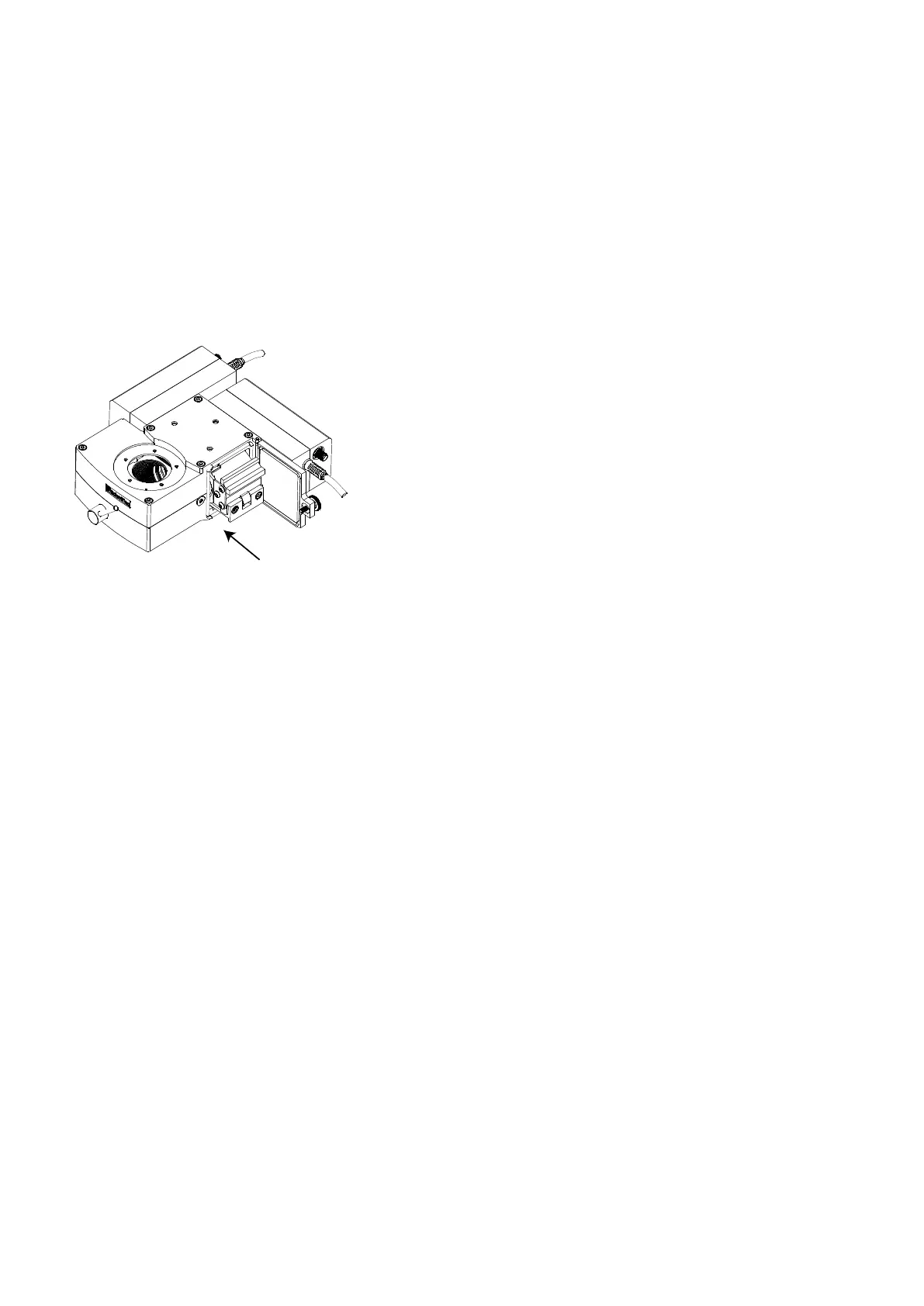
Two magnetically-retained sliders are provided, each having an M32 threaded hole which can accept an
objective lens directly or via the included reducing adapter rings. The sliders are guided into place by two rails
but located kinematically to ensure reproducible positioning.
U-MF2 filter cube
Figure D – U-MF2 filter cube is shown above mounted on its carrier
2.1.2 Detector module features
Each detector module is an integrated, self-contained unit which emits an analogue signal directly into the data
acquisition system. The detection system can be fitted with one or two detectors with spectral responses of
your choice.
The detector module incorporates a lens and stray light baffles that ensure optimum collection
efficiency whilst spreading the collected light across the sensitive surface. This avoids any problems
associated with bright spots or non-uniformity of response during a scan.
The detector is a photo-multiplier drawn from Hamamatsu’s R9880U or H1077x series.
The detector’s gain is controlled by an applied high-voltage (up to -1000 V); this bias is applied using a
miniature and integrated extra-low-noise power supply housed within the detector module. There is no
need for any separate or external power supplies.
The high-voltage is applied to the detector using an active voltage divider chain; this ensures that the
detector is maintained in a stable operating condition no matter what signals are being drawn from it –
the detector response is kept highly linear.
The detector’s output is connected directly to an integrated preamplifier with a gain of about 200,000
Volts per Amp (depending upon variant). Excess noise due to cables is therefore avoided.
The preamplifier is followed by a second-order constant delay / linear phase low-pass filter. (The cut off
frequency for low-pass filter comes with a choice of three pre-set factory options 0.25Mhz, 1.25Mhz or
no filter).This serves several purposes:
o Reducing noise and acting as an anti-alias filter for the data acquisition system
o Minimising scan-speed dependent distortions in the image – edges are cleanly rendered.