Page 16 of 58
3.0 Mechanical setup
This section details the mechanical, and in some cases optical, configuration required for the differing variants
of the MDU.
3.1 Fitting the above-stage MDU to the SliceScope
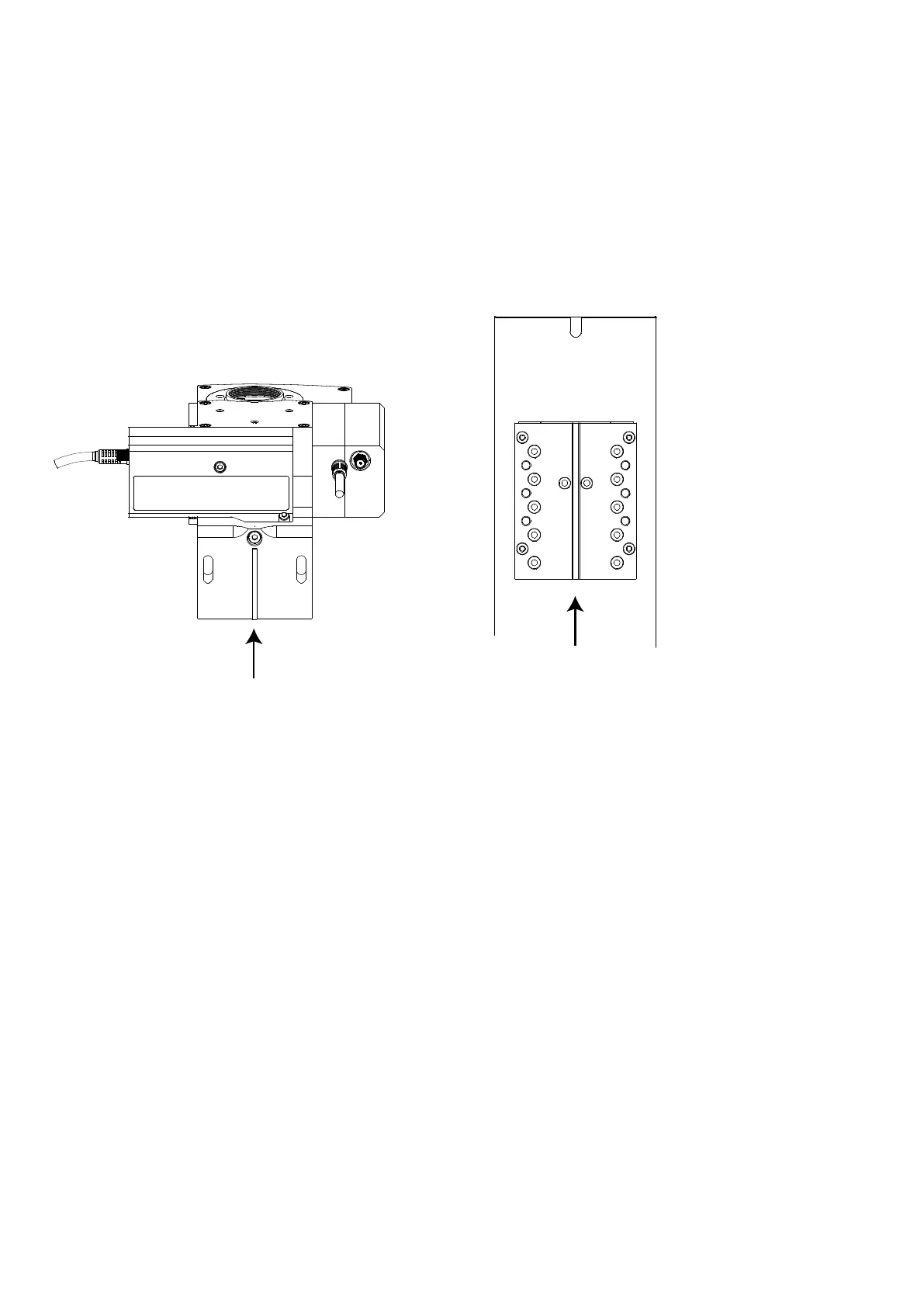
Figure F: Left: rear view of MDU above-stage variant with tongue indicated. Right: front view of Z-axis plate with
groove indicated.
The above-stage variant attaches to the upper focusing plate of the SliceScope via a bracket and two M5 X 25
mm hex cap-head bolts. The bracket has a narrow tongue that locates in a slot machined into the focus plate.
A 4 mm ball-head hex driver (supplied) is recommended for attaching the bracket to the SliceScope.
The main optical block is attached to its bracket using one M4 bolt and three M5
underneath the rear detector module. Refer to the procedure in the appendix for
module (
9.2 Detector Module removal)
The motorised focus plate on the SliceScope has three pairs of M5 tapped holes for attaching various parts.
The optical block should be attached using the central pair of holes (marked “A” in Figure F)). For
particular experimental requirements, it is possible to fit the optical block using the other sets of holes.
Support the optical block and offer it up to the motorised focus plate so that the tongue in the bracket
fits into the central groove in the focus plate.
Using a ball-ended hex driver, insert one M5 X 25 mm hex cap-head bolt through the slot in the bracket
so that it engages in the middle of the three M5 tapped holes on one side of the focus plate (marked
“A” in Figure F). Screw the bolt in until it stops but do not tighten it yet.
Insert the bolt on the other side and screw it in until it stops. Again, do not tighten it.
Allow the optical block to slide down on the slots in the bracket until the M5 bolt heads are at the top of
the slots as shown in Figure G.