Page 17 of 58
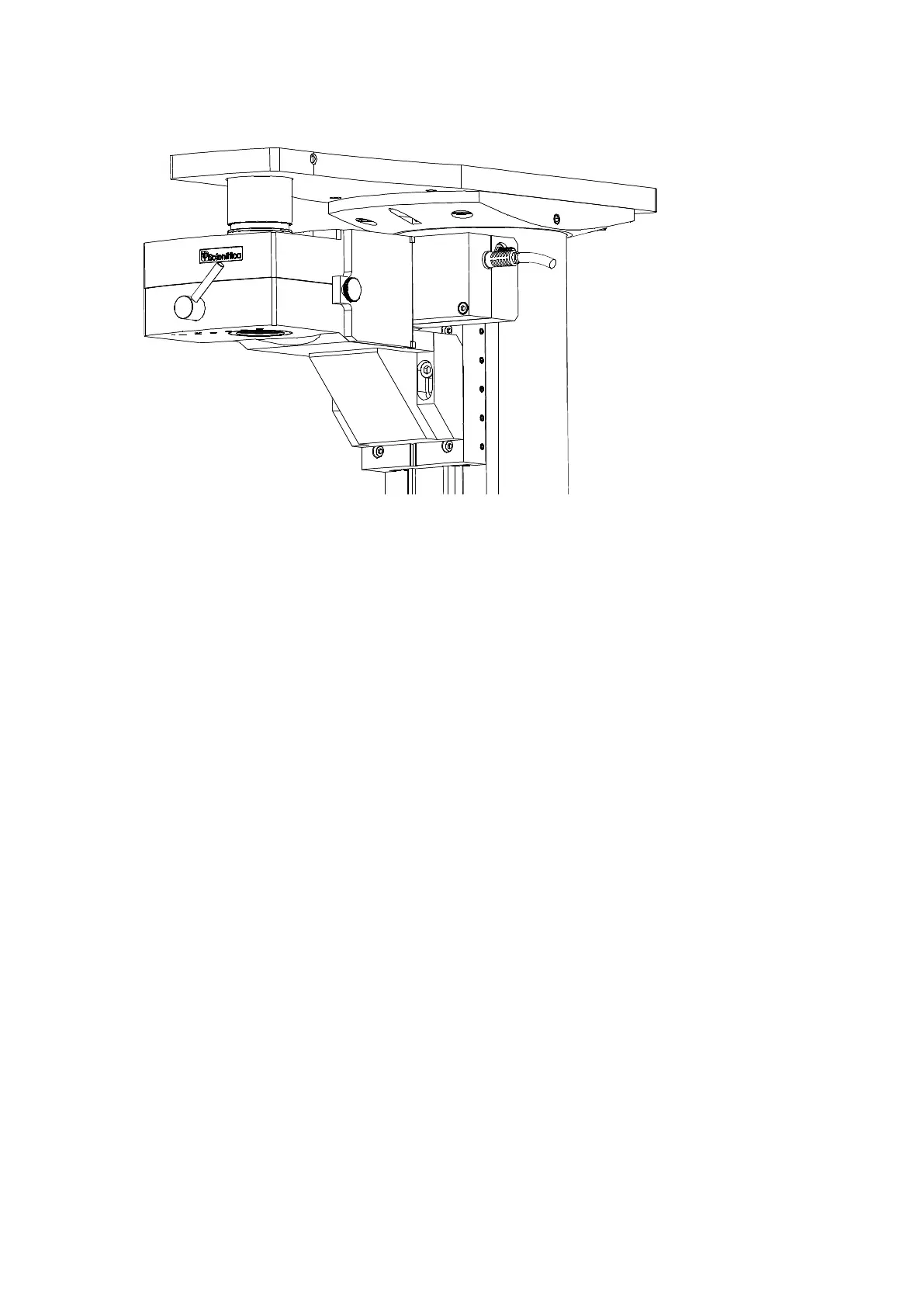
Figure G : Above-stage MDU fitted to the Z-focus plate: note the position of the bolt heads in the slots.
Unscrew the white plastic transit cover from the top entry port of the optical block; retain the cover for
shipping and storage. The threaded hole into which this cap was fitted is designed to accept a short
black plastic tube which acts as a light shield together with a second coaxial plastic tube. This tube
should be fitted only when the detector module has been fitted to the SliceScope frame. . (Ignore step if
Scanhead already present).
Locate the inner telescopic light-barrier tube and screw it into the top entry port of the optics block.
You may have to introduce the tube through the hole in the SliceScope’s top plate.
Locate the outer telescope tube (black plastic) and drop it down through the hole in the microscope top
plate so that it fits around the inner telescopic tube. (Please note if Scanhead present this tube would
already be present).
o If the fit between the tubes is tight, loosen both M5 fixing bolts slightly, and then gently tilt the
optical block from side to side to ease the fit of the tubes. When the fit is free, tighten both M5
bolts.
Test the vertical motion of the unit using the microscope controls and verify that full travel is available.
If the experiment height proves inconvenient, the height of the optical block can be adjusted by loosening the
M5 bolts through the bracket and sliding the module up and down. It is even possible to fit the boots through
the other sets of tapped holes in the motorised focus plate. Be aware that such changes may require the use
of different telescoping tubes and that laser beam delivery optics must be adjusted to suit.