Page 14 of 58
2.1.3 Control racks
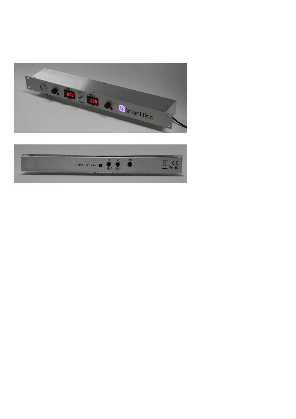
Figure D: Rack-mounting controller, front view
Figure E: Rack-mounting controller, rear view
The controller is supplied as a 1U height rack-mounted unit. The main power switch is a push-button
on the far left of the front panel.
DC input comes from a universal input mains power converter via a 2.5 mm DC plug on the rear panel.
The total current required is about 0.5 Amps at 12V DC. The centre pin of the connector is positive,
and the outer ring is connected to ground.
Two 8-pin Mini-DIN sockets (labelled “PMT A” and “PMT B”) are provided on the rear panel. Cables
from the two detector modules are connected here. Non-locking connectors are used to prevent
damage if the cables are pulled by accident; ensure that both connectors are pushed firmly home.
One 6-pin mini-DIN connector (marked “PD”) is provided on the rear panel: this is intended to supply
power to a photodiode module for transmitted laser imaging (available as an optional add-on). Do not
attempt to connect the main detectors cables to this socket – it is not compatible!
Two small LED display meters are provided on the front panel, together with two rotary controls. The
controls adjust the high voltage applied to each PMT detector independently in the range 0V to about -
1000V. The gain of each detector rises as a power function of the applied voltage. The meters
continuously display the high voltage actually applied to each PMT when the interlocks and the master
safety switch permit.
A “master safety” switch is provided on the centre of the front panel. This switch is of a special type
that cannot be actuated accidentally – the toggle must be pulled outwards whilst the switch position is
changed.
o When in the “safe” (up) position, no high voltage can be applied to either PMT. The displays
read nearly zero or a small positive voltage.
o When in the “Enable” (down) position, high voltage can be applied to the PMTs if the other
interlocks are not activated (laser-visible dichroic mirror position and filter cube door). The