Page 35 of 58
3.6 Filter Cube Installation
The filter cube is used to enable simultaneous two-channel detection (by means of a dichroic mirror / beam-
splitter) and to define the spectral responses of each channel (by means of appropriate band-pass interference
filters). Use of the filter cube is not mandatory: for single-channel operation no cube is required. Two-
channel operation however requires at least a dichroic mirror to be installed in the cube to enable the second
detector to receive some light.
A single, un-populated Olympus U-MF2 filter cube is supplied with each detection system. The cube can
accept standard-sized fluorescence optical filter sets to suit the experimental requirements. Two 25 mm
interference-type filters can be accommodated using screw-in retaining rings (which can accept thin or thick
filters). Any Olympus-standard pre-populated filter cube will fit into the system.
The filter cube must be located precisely within the optical block for efficient operation; a suitable carrier is
provided which slides into a compartment within the optical block behind an access door on the right-hand
side. The base of the carrier incorporates a dovetail slide for positioning.
3.6.1 Filter Cube Population
The filter cube should be populated according to the instructions supplied by Olympus and using the tools
supplied.
It is assumed that the filter cube will be configured to transmit longer wavelengths and to reflect shorter
wavelengths via the side-arm. See the cautions below.
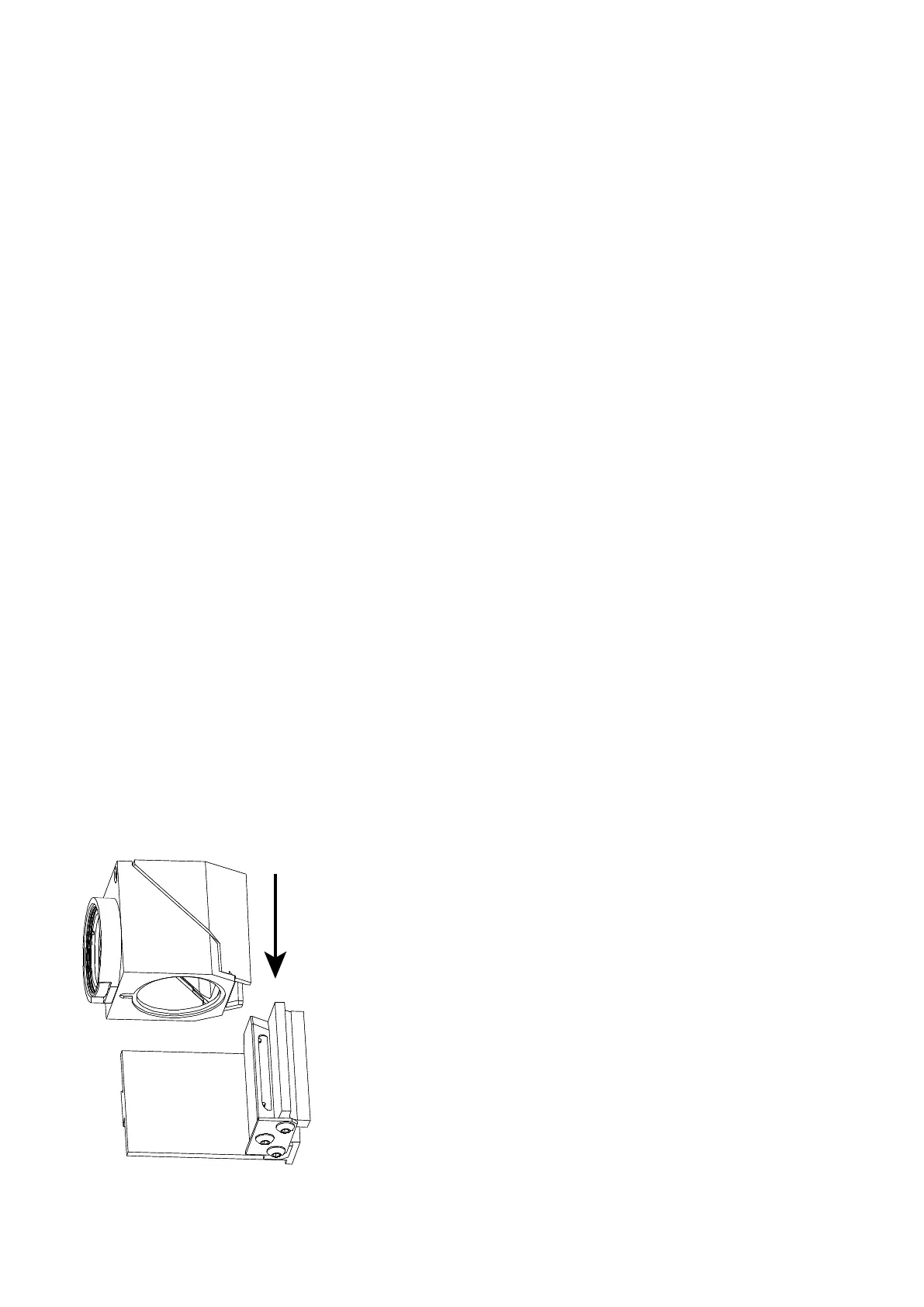
3.6.2 Fitting the cube to the carrier
The populated filter cube fits onto the carrier via a sprung-loaded dove-tail mount. Begin by aligning the cube
and the carrier as shown in the figure: the black plastic face of the cube with an open aperture must face the
open end of the dove-tail slide. The other end of the slide is blocked by a stopping plate held on by three
screws.
Figure X: Fitting cube to the carrier