BEFORE CONNECTING THIS JOINTER TO THE POWER SUPPLY, VERIFY THAT THE SUPPLY VOLTAGE MATCHES THAT OF
THE MOTOR. INCORRECT SUPPLY VOLTAGE CAN RESULT IN SERIOUS INJURY TO THE USER AND DAMAGE TO THE MA-
CHINE. IF YOU ARE UNSURE OF THE SUPPLY OR EQUIPMENT VOLTAGE, CONTACT A QUALIFIED ELECTRICIAN BEFORE
ATTEMPTING TO USE THE JOINTER. DO NOT EXPOSE THIS TOOL TO RAIN OR USE IT IN WET OR DAMP LOCATIONS.
Electrical Requirements
If you are unsure about whether or not your receptacle
is grounded, check with a qualied electrician or service
person.
Circuit Capacity
Make sure that the circuit used to power your jointer is
properly sized to handle the jointer and any other equip-
ment that is powered by the circuit. If the circuit breaker
trips regularly, equipment connected to the circuit is
drawing more amperage than the breaker can handle.
Move some equipment to another circuit or have a
licensed electrician install a higher capacity circuit. If the
circuit is not overloaded and the breaker continues to trip
when the jointer is used, there may be a fault with the
motor. Contact a licensed electrician or CWI.
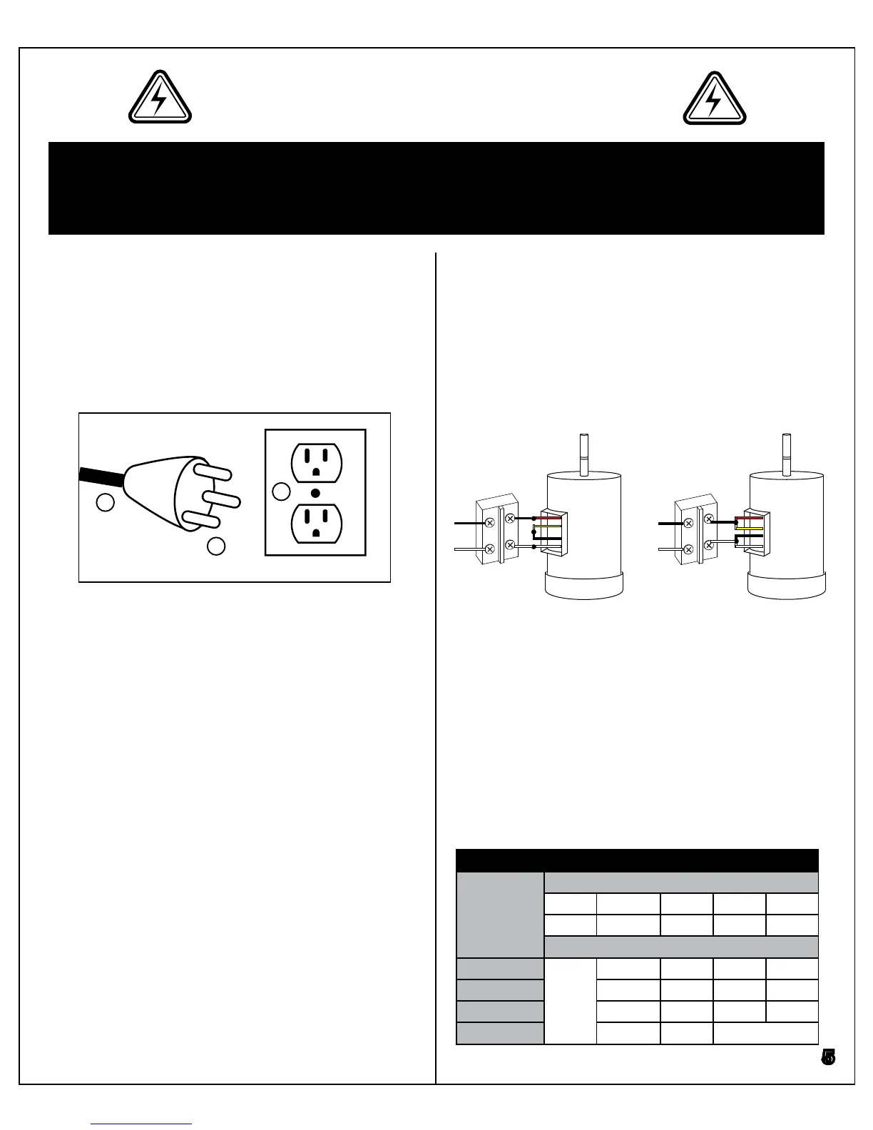
Converting the Jointer to 240V
The motor is pre-wired for use with a 120VAC power
supply. The jointer can be converted for use with 240V
single phase, but it is recommended that a qualied
electrician perform this conversion. Follow the wiring
diagram below to change the motor to 240V. It is also
recommended to change the jointer’s plug to a NEMA
6-15P type plug to prevent accidental usage on a 120V
circuit.
Minimum Wire Size of Extension Cord
Equipment
Current
Rating
(Amperes)
Length of extension cord (feet)
115V 25 50 100 150
230V 50 100 200 300
Wire size (AWG)
5 or less 18 16 16 14
6-10 18 16 14 12
10-12 16 16 14 12
12-16 14 12
Not recommended
C
B
A
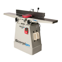
Grounding Instructions
In the event of an electrical malfunction or short circuit,
grounding reduces the risk of electric shock to the op-
erator. The motor of this machine is wired for 120V and
is equipped with a 3-conductor cord (A) and a 3-prong
grounded plug (B) to t a matching grounding type re-
ceptacle (C).
Extension Cords
If you need to use an extension cord to power the joint-
er, always use a 3-prong extension cord with ground-
ing pin and a matching 3-prong receptacle. Repair or
replace a damaged extension cord or plug immediately.
Make sure the cord rating is suitable for the amperage
listed on the motor ID plate. An undersized extension
cord will cause a drop in line voltage resulting in loss
of power and dangerous overheating of the extension
cord. The table below shows the recommended mini-
mum wire size for extension cord usage. The smaller
the number, the heavier the gauge.
5
120V240V
Switch Switch
Motor Motor
To PlugTo Plug