1993-97 Chrysler Concorde
Read pages 2-4
for kit assembly.
1993-00 Dodge Intrepid
1993-97 Eagle Vision
RADIO REMOVAL:
1. Pull the radio trim bezel out to release the snap clips, and remove the bezel.
2. Extract the two bolts securing the radio, pull the radio from the cavity, unplug all
connectors and remove the radio.
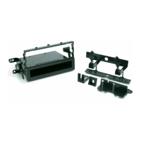
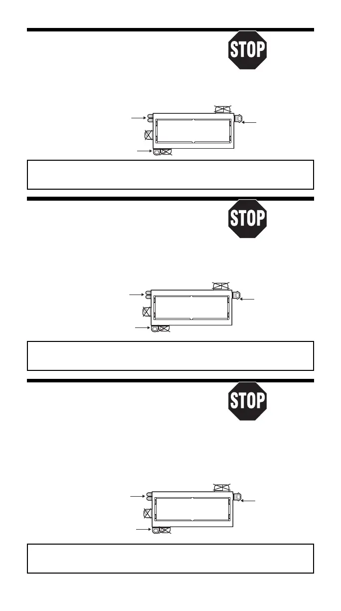
USE THESE SUPPORT TABS AS REQUIRED
Usar tantas de estas pestañas como sea
necesario
USE THIS BRACKET
Usar este braquete
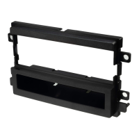
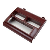
#2190 PANEL
REMOVE ALIGNMENT
PIN - BOTTOM
Sacar la clavija de
alineamiento - Inferior
USE THE SHADED MOUNTING TABS AND THE INDICATED BRACKETS. CUT OFF THE REMAINING TABS AND
DISCARD. FOR DIN ISO INSTALLATION, SEE PAGE 4.
Usar las pestañas sombreadas y los braquetes indicados. Cortar las pestañas restantes y descartarlas.
Para la instalación de radios DIN ISO ver la página 4.
1980-83 Chrysler Cordoba
Read pages 2-4
1980-83 Dodge Mirada
for kit assembly.
RADIO REMOVAL:
1. Remove four screws securing the radio dash panel:
two above the radio and two above the heater controls.
2. Remove the radio dash panel. Remove two screws securing the radio to the dash.
Pull the radio out.
3. Disconnect power, antenna, and all speaker and electrical connections.
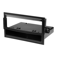
#2190 PANEL
REMOVE ALIGNMENT
USE THESE SUPPORT TABS AS REQUIRED
PIN - BOTTOM
Usar tantas de estas pestañas como sea
Sacar la clavija de
alineamiento - Inferior
necesario
USE THIS BRACKET
Usar este braquete
USE THE SHADED MOUNTING TABS AND THE INDICATED BRACKETS. CUT OFF THE REMAINING TABS
AND DISCARD. FOR DIN ISO INSTALLATION, SEE PAGE 4.
Usar las pestañas sombreadas y los braquetes indicados. Cortar las pestañas restantes y descartarlas.
Para la instalación de radios DIN ISO ver la página 4.
1975-79 Chrysler Cordoba
Read pages 2-4
for kit assembly.
1975-79 Plymouth Fury
RADIO REMOVAL:
1. Remove four securing screws from the bottom edge
of the radio dash panel.
2. Remove two securing screws from the top edge of the panel above the radio.
3. Unscrew the retainer ring securing the remote mirror control and remove the panel.
4. Remove two screws securing radio to the dash. Pull the radio out.
5. Disconnect power, antenna and all speaker and electrical connections.
USE THESE SUPPORT TABS AS REQUIRED
#2190 PANEL
REMOVE ALIGNMENT
Usar tantas de estas pestañas como sea
PIN - BOTTOM
necesario
Sacar la clavija de
alineamiento - Inferior
USE THIS BRACKET
Usar este braquete
USE THE SHADED MOUNTING TABS AND THE INDICATED BRACKETS. CUT OFF THE REMAINING TABS
AND DISCARD.FOR DIN ISO INSTALLATION, SEE PAGE 4.
Usar las pestañas sombreadas y los braquetes indicados. Cortar las pestañas restantes y descartarlas.
Para la instalación de radios DIN ISO ver la página 4.
6
 Loading...