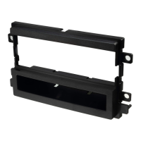
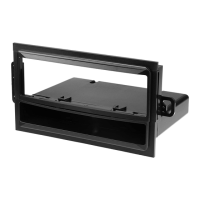
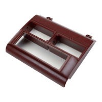
#2190 PANEL
Read pages 2-4
for kit assembly.
Read pages 2-4
for kit assembly.
Read pages 2-4
for kit assembly.
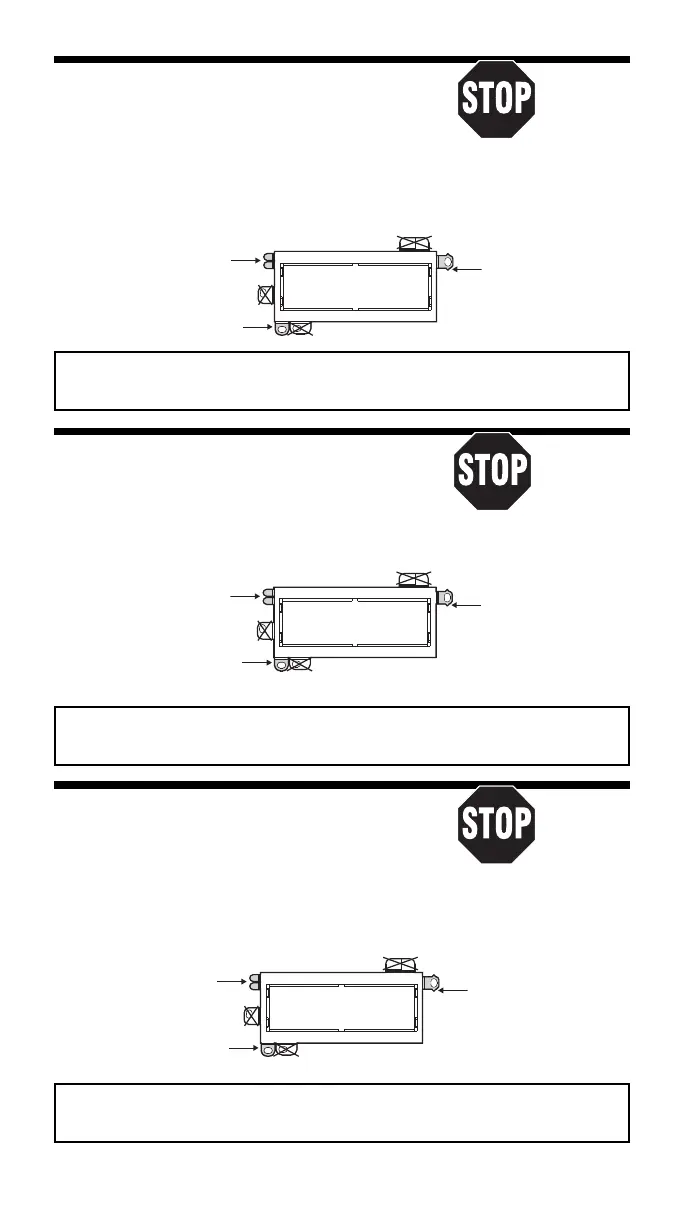
REMOVE ALIGNMENT
TABS AS REQUIRED
1987-93 Chrysler Le Baron “Coupe”
Read pages 2-4
for kit assembly.
RADIO REMOVAL:
1. Remove two screws, one from each lower corner
of the radio/console trim panel.
2. Gently snap off the trim panel.
3. Remove two screws securing the right side panel of the console, one at top, one at bottom;
remove the side panel.
4. Remove two screws from the radio mounting bracket. Disconnect the wire harness, antenna
lead, and ground strap. Remove the radio.
USE THESE SUPPORT
PIN - BOTTOM
Sacar la clavija de
pestañas como sea
Usar tantas de estas
alineamiento - Inferior
necesario
USE THIS BRACKET
Usar este braquete
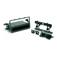
USE THE SHADED MOUNTING TABS AND THE INDICATED BRACKETS. CUT OFF THE REMAINING TABS
AND DISCARD. FOR DIN ISO INSTALLATION, SEE PAGE 4.
Usar las pestañas sombreadas y los braquetes indicados. Cortar las pestañas restantes y descartarlas.
Para la instalación de radios DIN ISO ver la página 4.
1990-95 Chrysler Le Baron GTC
Read pages 2-4
for kit assembly.
RADIO REMOVAL:
1. Gently pry outward on the radio trim bezel
to release seven snap clips and remove.
2. Extract two hex head bolts holding radio in place and slide radio outward.
3. Unplug all power/speaker connectors, unplug antenna and unbolt ground strap-remove radio.
USE THESE SUPPORT
TABS AS REQUIRED
Usar tantas de estas
pestañas como sea
necesario
USE THIS BRACKET
Usar este braquete
#2190 PANEL
REMOVE ALIGNMENT
PIN - BOTTOM
Sacar la clavija de
alineamiento - Inferior
1985-89 Chrysler Le Baron GTS
Read pages 2-4
for kit assembly.
1985-89 Dodge Lancer
RADIO REMOVAL:
1. Remove eleven screws from the perimeter of the
dash trim panel and remove the trim panel.
USE THE SHADED MOUNTING TABS AND THE INDICATED BRACKETS. CUT OFF THE REMAINING TABS
AND DISCARD. FOR DIN ISO INSTALLATION, SEE PAGE 4.
Usar las pestañas sombreadas y los braquetes indicados. Cortar las pestañas restantes y descartarlas.
Para la instalación de radios DIN ISO ver la página 4.
2. Remove two anti-theft bolts (use Snap-On bit TTW12 for 1/4'' drive) which secure the radio
to the dash substructure; pull the radio out of the cavity, disconnect all wiring,
and remove the radio.
#2190 PANEL
REMOVE ALIGNMENT
TABS AS REQUIRED
USE THESE SUPPORT
PIN - BOTTOM
Sacar la clavija de
pestañas como sea
Usar tantas de estas
alineamiento - Inferior
necesario
USE THIS BRACKET
Usar este braquete
USE THE SHADED MOUNTING TABS AND THE INDICATED BRACKETS. CUT OFF THE REMAINING TABS
AND DISCARD. FOR DIN ISO INSTALLATION, SEE PAGE 4.
Usar las pestañas sombreadas y los braquetes indicados. Cortar las pestañas restantes y descartarlas.
Para la instalación de radios DIN ISO ver la página 4.
9
 Loading...