P:\ INST INSTRUCTIONS\ACCESS CONTROLS\INST-918 REV D 11-21 Page 2
QuickStart Programming
To enter Programming Mode, enter #9# Master Code#. The yellow indicator will blink slowly showing that the 918 EntryCheck™ is in
programming mode. Use the option codes to program the each function. After the new data entry is complete for each function , the
yellow indicator will flash quickly while the data is being stored and the green indicator will light briefly if the programming has been
accepted. The red indicator will light if any programming data is entered incorrectly or the function is rejected. If a red indicator is seen,
the entire function (option code + data) will have to be fully re-entered.
Test your new user code
Enter user code ‘9876’. After pressing the last digit, the green indicator should illuminate,
and the main relay should activate and the door should unlock for 5 seconds.
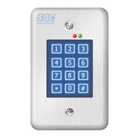
KEYPAD
RED/GREEN
POWER/ACCESS
INDICATOR
YELLOW
“LOCKOUT/
PROGRAM”
INDICATOR
TERMINAL
BLOCK #1
(TB1)
MOUNTING
PLATE
BEEPER
LEVEL
JUMPER
(JP1)
WIRE
HARNESS
(E1-E8)
MASTER CODE
RESET JUMPER
(JP2)
Fig. 1 Keypad
Program the first user code
Step 1. Enter: #9# 123456# Enter the program mode (default master code = 123456)
Step 2. Enter: 03# 4# Set the entry code length to 4 digits
Step 3. Enter: 21# 5# Set the main relay activate time to 5 sec.
Step 4. Enter: 01# 9876# 9876# 1# Set user code ‘9876’ to activate the main relay
Step 5. Enter: # Exit programming mode
**
Adding additional user codes
Once the code length and relay time have been set you do not need to set them each
time you additional users.
To add additional users:
Step 1. Enter: #9# 123456# Enter the program mode (default master code)
Step 2. Enter: 01# 2222# 2222# 1# Set user code ‘2222’ to activate the main relay
Step 3. Enter: 01# 3333# 3333# 1# Set user code ‘3333’ to activate the main relay
Step 4. Enter: # Exit programming mode
**
Deleting a user code
To delete a user:
Step 1. Enter: #9# 123456# Enter the program mode (default master code)
Step 2. Enter: 02# 3333# 3333# User code ‘3333’ has been deleted.
Step . Enter: # Exit programming mode
**
SECURITY DOOR CONTROLS ■ WWW.SDCSECURITY.COM
[t] 800.413.8783 ■ 805.494.0622 ■ E-mail: service@sdcsecurity.com ■ 801 Avenida Acaso, Camarillo, CA 93012 ■ PO Box 3670, Camarillo, CA 93011
CAUTION
IF THE UNIT IS AC POWERED, MAKE SURE
THAT THE SECONDARY OF THE SYSTEM IS
ISOLATED FROM EARTH GROUND
!
!
Fig. 2 Wiring Diagram
E1
E2
E3
E4
E5
E6
E7
E8
AUXILIARY RELAY
2 AMPS @ 28VDC MAX
TO POWER SUPPLY
FAIL SECURE CONNECTION
+
-
KEY PAD POWER
12/24 VOLTS
DC or AC
SENSE
GROUND
REQUEST TO EXIT
GROUND
GROUND
OUTPUT 3
OUTPUT 4
GROUND
BLACK
GREEN
BLUE
BLACK
BLACK
VIOLET
BLACK
GRAY
FAIL SAFE CONNECTION
MAIN RELAY
5 AMPS @ 28VDC MAX
C
N/O
N/C
C
N/O
N/C
N/C DOOR
POSITION
SWITCH
N/O
REQUEST-
TO-EXIT
SWITCH
EARTH
GROUND
CONNECTION
AUXILIARY OUTPUTS
100mA MAX TO COMMON
918 TERMINALS
NO
COM
NC
NO
NC
COM
}
}
}