A
ajarvisAug 3, 2025
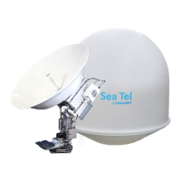
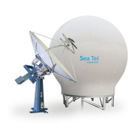
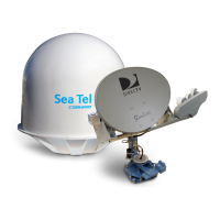
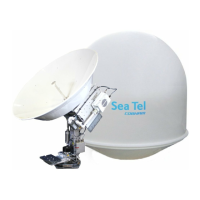
How to perform mechanical checks on Sea Tel 9797B-76 Antenna?
- GGarrett MartinezAug 3, 2025
To ensure proper functionality, inspect the inside of the Sea Tel Antenna radome for any signs that the dish or feed have been rubbing against the fiberglass. Rotate the pedestal through its full range of azimuth, elevation, and cross-level motion; the antenna should rotate freely and easily with light finger pressure. Also, rotate the level cage through the full 90 degrees of rotation, ensuring attached cables don't cause the cage to spring back more than a few degrees from either stop when released. Inspect all drive belts for wear and the AZ Drive chain, applying a light coat of light duty oil if rust or corrosion are present, but avoid over-lubrication.