EasyManua.ls Logo

Sea Tel 9711-92 - User Manual

Sea Tel 9711-92
196 pages
Print Icon
To Next Page IconTo Next Page
Loading...
Sea Tel, Inc.
4030 Nelson Avenue
Concord, CA 94520
Tel: (925) 798-7979
Fax: (925) 798-7986
Web: http://www.cobham.com/seatel
Sea Tel Europe
Unit 1, Orion Industrial Centre
Wide Lane, Swaythling
Southampton, UK S0 18 2HJ
Tel: 44 (0)23 80 671155
Fax: 44 (0)23 80 671166
Web: http://www.cobham.com/seatel
Sea Tel Inc is also doing business as Cobham SATCOM - Maritime
April 8, 2014 Document. No. 139192 Revision A2
INSTALLATION AND OPERATION MANUAL
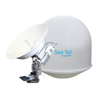
FOR SEA TEL MODEL
9711-92 KU-BAND TX/RX ANTENNA
WARNING: RF RADIATION HAZARD
This stabilized antenna system is designed to be used with transmit/receive equipment
manufactured by others. Refer to the documentation supplied by the manufacturer which
will describe potential hazards, including exposure to RF radiation, associated with the
improper use of the transmit/receive equipment. Note that the transmit/receive
equipment will operate independently of the stabilized antenna system. Prior to work on
the stabilized antenna system, the power to the transmit/receive system must be locked
out and tagged.
When the transmit/receive system is in operation, no one should be allowed anywhere
within the radiated beam being emitted from the reflector.
The ultimate responsibility for safety rests with the facility operator and the
individuals who work on the system.

Table of Contents

Questions and Answers

Summary

1. Introduction

1.1. General System Description

Provides an overview of the fully stabilized antenna system designed for reliable, easy operation and maintenance.

1.4. System Components

Details the two main groups of equipment: Above-Decks Equipment (ADE) and Below-Decks Equipment (BDE).

1.5. Dual Antenna Configuration

Explains the setup for a dual antenna configuration to provide uninterrupted services, often used with blockage conditions.

1.6. Dual Antenna Arbitrator

Describes the function of the Dual Antenna Arbitrator panel for managing signal switching between two antennas.

1.7. Open Antenna-Modem Interface Protocol (OPENAMIP) Specification

Details the OpenAMIP™ protocol for communication between an antenna controller and a satellite modem.

3. Installation

3.1. General Cautions & Warnings

Provides crucial safety warnings, tightening torque values, and Loctite recommendations for installation.

3.2. Unpacking the Base Frame and Reflector Crate

Instructions for safely unpacking the base frame, reflector, feed assembly, and hardware kit from the crate.

3.3. Assembling the ADE

Step-by-step guide for sub-assembling the Base Frame Assembly and Radome Assembly for the ADE.

3.4. Installing the ADE

Procedures for hoisting and installing the assembled Antenna/Radome/Baseframe onto the ship.

3.5. Installing the Below Decks Equipment

Guidance on preparing the location and installing Below Decks Equipment like ACU, TMS, and modems.

3.6. Connecting the Below Decks Equipment

Detailed instructions for connecting AC power, IF coaxes, modem, and other cables for BDE.

3.11. Power-Up the ADE

Steps for powering up the antenna pedestal, including initialization and home flag position.

4. Basic Setup of the ACU

4.1. Operator Settings

Guidance on setting ship information, satellite, and receiver settings for initial operation.

4.3. Default Setup Parameters for your Antenna

Lists factory default parameters for the DAC-2202 ACU and guidance on optimizing them.

5. Setup - Ships Gyro Compass

5.1. Gyro Type

Explains how to select the correct GYRO TYPE parameter for the ship's gyro compass interface signal.

5.3. If there is NO Ships Gyro Compass

Provides instructions for configuring the system when no gyro compass input is available.

6. Setup - Band Select

6.1. TRACK DISP

Parameter to set user selections in the Tracking - Band Selection menu for proper tracking.

7. Setup - Tracking Receiver - VSAT

7.1. Determining the IF Tracking Frequency (MHZ)

Explains how to determine and enter the IF Tracking frequency value for the ACU.

7.3. FEC

Specifies the Forward Error Correction rate setting for the L-Band SCPC Receiver.

8. Setup - Home Flag Offset

8.1. Electronic Calibration of Relative Antenna Position (Home Flag Offset)

Details the procedure for calibrating the antenna's relative azimuth to the ship's bow line.

9. Setup - Targeting

9.1. AUTO TRIM

Procedure to automatically calculate and set Azimuth and Elevation trim offset parameters.

9.2. Manually Optimizing Targeting

Steps for manually adjusting Azimuth and Elevation trim for optimal satellite targeting.

10. Setup - Searching

10.1. Searching Operation

Describes the automated search pattern initiated after AGC signal loss and search parameters.

10.2. Changing the Search Parameters

Provides information on adjusting parameters like AUTO THRES, EL STEP SIZE, AZ STEP SIZE, and STEP INTEGRAL.

11. Setup - Blockage & RF Radiation Hazard Zones

11.1. Radiation Hazard and Blockage Mapping (AZ LIMIT parameters)

Explains how to program relative azimuth sectors (zones) for blockage and RF hazard mapping.

12. Setup - Modem Connections, Setup and Test

12.1. Jumper Selection

Guides through selecting jumpers for various modem functions like Band Select and TX Mute control.

12.7. SYSTEM TYPE parameter

Details the SYSTEM TYPE parameter for enabling various system functions like AGC, LNB Voltage, and Blockage.

12.8. Blockage Simulation Test - DAC-2202

Describes how to test the blockage output function using SW2 trigger states.

12.9. Testing the Satellite Modem Lock Input - DAC-2202

Provides steps to test the external AGC input and monitor modem lock status.

13. Setup -Optimizing Ku-Band Polarity and Cross-Pol Isolation

13.1. Polarity Angle (POLANG) Parameters

Ensures correct setting of POL TYPE, POL OFFSET, and POL SCALE parameters for polarization.

13.2. Optimizing Auto-Polarization on Receive Signal

Procedure to optimize linear polarization based on received signal level using SAT SKEW.

13.3. Optimizing Auto-Polarization Cross-Pol Isolation

Adjusting to minimize transmission effect on opposite polarization for maximum Cross-Pol isolation.

14. Setup - Other Parameters

14.1. SETUP Parameter display and entry menus.

Instructions on accessing system setup parameters and the SAVE NEW PARAMETERS function.

14.6. Satellite Reference Mode

Explains how to enable/disable Satellite Reference Mode for gyro compass input issues.

15. Antenna Specific Operation

15.1. System Power-up

Instructions for turning on the antenna pedestal power and the ACU power switch.

15.2. Antenna Initialization

Details the sequence of steps for antenna pedestal initialization after power-up.

15.5. Manually Targeting A Different Satellite

Guidance on manually changing settings to target a different satellite if not using remote access.

16. Functional Testing

16.1. ACU; Antenna System Check

Verifies ACU and antenna system response to key presses and basic functionality.

16.5. Four Quadrant Tracking Test

Tests tracking by driving the dish in four quadrants to ensure peak satellite signal level.

16.6. Blockage Simulation Test

Tests the blockage function by simulating a blocked condition and verifying SW2 terminal output.

17. Installation Troubleshooting

17.1. Troubleshooting the ACU

Lists common ACU problems like blank display or 'REMOTE NOT RESPONDING' and their solutions.

17.2. Troubleshooting Ships Gyro Compass problems

Addresses issues where the ship's heading display does not follow movement or shows ERROR CODE 0001.

17.3. Troubleshooting

Provides a framework for troubleshooting by classifying faults into Targeting, Stabilization, and Tracking.

18. Maintenance

18.1. Warranty Information

Details the two-year limited warranty coverage for the antenna system and exclusions.

18.3. General Maintenance

Covers general maintenance tasks including antenna balancing and motor drive torque monitoring.

18.4. 400 MHz Modem Configuration

Explains jumper settings for the 400MHz modem to configure serial protocol and mounting location.

18.8. Installing and Calibrating the Ku-Band Co-Pol & Cross-Pol Feed

Procedure for installing and calibrating the Ku-Band Co-Pol/Cross-Pol feed assembly on the reflector.

19. Stowing the Antenna

19.1. Installing the Stow Restraints

Instructions for properly restraining the antenna pedestal when underway and power is removed.

20. Bluetooth Installation & Operation

20.1. Prerequisites

Lists minimum system requirements for using a Bluetooth device with the antenna system.

20.2. Installing the ADE Bluetooth Hardware

Step-by-step guide for installing the Bluetooth dongle into the Above-Decks Equipment (ADE).

20.3. Installing the BDE Bluetooth Hardware

Instructions for installing the Bluetooth transmitter on the Below-Decks Equipment (BDE) computer.

20.5. Removing the ADE Bluetooth Hardware

Procedure for safely removing the Bluetooth hardware from the ADE.

21. 9711-92 Technical Specifications

21.1. 9711-92 Specifications

Provides detailed technical specifications for the Above Decks Equipment, including weight, motors, and ranges.

21.2. Cables

Details specifications for antenna control, transmit/receive IF coax, and multi-conductor cables.

21.3. Regulatory Compliance

Lists regulatory compliance standards and certifications for Ku-Band antenna systems.

22. Drawings

22.1. 9711-92 Model Specific Drawings

Lists specific drawings for the 9711-92 model, including system, schematic, and assembly diagrams.

22.2. 9711 General Drawings

References general drawings for components like the Terminal Mounting Strip and Modem Rack Panel.

Sea Tel 9711-92 Specifications

General IconGeneral
Frequency BandKu-band
PolarizationLinear
Stabilization3-axis
Environmental RatingIP66
Reflector TypeParabolic
CompatibilityGlobal Ku-band satellites
Mount TypePedestal

Related product manuals