EasyManua.ls Logo

Sea Tel Cobham 4009-91 MK3 - User Manual

Sea Tel Cobham 4009-91 MK3
114 pages
Print Icon
To Next Page IconTo Next Page
Loading...
Sea Tel, Inc.
4030 Nelson Avenue
Concord, CA 94520
Tel: (925) 798-7979
Fax: (925) 798-7986
Web: http://www.cobham.com/seatel
Sea Tel Europe
Unit 1, Orion Industrial Centre
Wide Lane, Swaythling
Southampton, UK S0 18 2HJ
Tel: 44 (0)23 80 671155
Fax: 44 (0)23 80 671166
Web: http://www.cobham.com/seatel
Sea Tel Inc is also doing business as Cobham Antenna Systems
February 15, 2013 Document. No. 138683 Revision A
INSTALLATION MANUAL
FOR SEA TEL 4009-91MK3 KU-BAND
BROADBAND-AT-SEA VSAT ANTENNA SYSTEM

Table of Contents

Question and Answer IconNeed help?

Do you have a question about the Sea Tel Cobham 4009-91 MK3 and is the answer not in the manual?

Summary

09 Series System Configuration

System Cables

Discusses AC Power & Coaxial cable routing and installation.

Other Inputs to the System

Describes connections for Gyro Compass, GPS, phone, fax, and computers.

Simplified Block Diagram

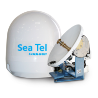
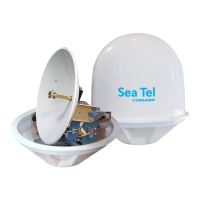
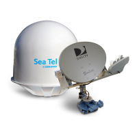
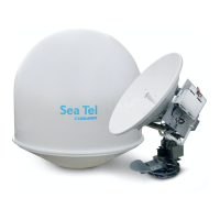
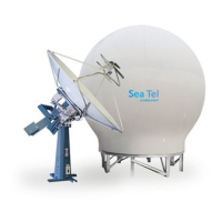
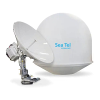
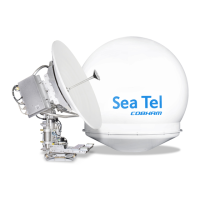
Illustrates the two major equipment groups: Above Decks (ADE) and Below Decks (BDE).

Dual Antenna Configuration

Explains setting up two antennas for uninterrupted service during blockage conditions.

Open Antenna-Modem Interface Protocol (OpenAMIP) Specification

Overview

Defines OpenAMIP™ as an ASCII message protocol for modem-controller communication.

Interface Requirements

Details hardware and software requirements for OpenAMIP™ interface compatibility.

Site Survey

Site Selection Aboard The Ship

Guidelines for choosing an optimal mounting location for the antenna on a vessel.

Antenna Shadowing and RF Interference

Addresses potential signal degradation due to physical obstructions and RF interference.

Mounting Foundation

Mounting on Deck or Deckhouse

Discusses mounting the antenna directly on a deck or deckhouse structure.

ADE Mounting Considerations

Specific points to consider when mounting the Above Decks Equipment (ADE) radome.

Sizing of the Support Pedestal

Factors to consider when determining the appropriate size and strength of the support pedestal.

Mounting Height

Mast Configurations

Vertical Masts

Describes vertical masts and preferred/alternate mounting arrangements for the ADE.

Raked Masts

Discusses raked masts, their aesthetic purpose, and mounting challenges.

Girder Masts

Explains girder masts and their stiffness characteristics relevant to antenna mounting.

Truss Mast

Safe Access to the ADE

Below Decks Equipment Location

Cables

ADE;BDE Coaxial Cables

Specific advice on installing coaxial cables between ADE and BDE, focusing on loss and connector quality.

Antenna Power Cable

Instructions for routing and installing the antenna power cable, considering voltage loss and circuit arrangement.

Air Conditioner Power Cable

Guidance on running the AC power cable for the marine air conditioner, if applicable.

ACU Power Cable;Outlet

Recommendations for ACU and other below decks equipment power cabling.

Gyro Compass Cable

Best practices for selecting and installing shielded cable for gyro compass connections.

Grounding

Installation

Unpacking and Inspection

Steps for safely unpacking and inspecting the antenna system components for shipping damage.

Assembly Notes and Warnings

Important notes on using Loctite, tightening torque values, and hoisting precautions.

Installing the ADE

Prepare the 50”, 60”, 66” or 76” Radome Assembly

Instructions for preparing the radome assembly for installation, including removing shipping bolts.

Installing the 50, 60 or 66” Radome Assembly

Grounding the Pedestal

Removing Shipping;Stow Restraints

Removing the AZ Shipping;Stow Restraint

Procedure for removing the Azimuth (AZ) shipping and stowage restraint pin.

Removing the EL Shipping;Stow Restraint

Removing the CL Shipping;Stow Restraint

Installing the Below Decks Equipment

General Cautions & Warnings

Safety precautions regarding electrical shock and unauthorized installation or service.

Connecting the ADE AC Power Cable

How to connect the AC power cable for the Above Decks Equipment (ADE).

Connecting the BDE AC Power Cables

How to connect AC power cables for Below Decks Equipment (BDE).

Media Xchange Point (MXP) Connections

Details on connecting various interfaces and peripherals to the MXP.

Other BDE connections

Final Checks

Visual;Electrical Inspection

Performing a visual check to ensure all connections are secure and properly made.

Electrical - Double check wiring connections

Verifying all wiring connections are safe before energizing the equipment.

Setup - Media Xchange Point (MXP)

Configuring a Computer for the MXP

Setup - Ship’s Gyro Compass

Setting the Gyro Type

Selecting the correct gyro compass interface type for accurate heading input.

If there is NO Ships Gyro Compass

Setup - Satellite Configuration

Setup - Home Flag

You Found a Large AZ TRIM value

Adjusting the Home Flag value when a large AZ TRIM has been previously used for calibration.

You Observe “Home” Pointing is LEFT of the Bow-line

You Observe “Home” Pointing is RIGHT of the Bow-line

Entering a large value as Home Flag

Entering a small value as AZ TRIM

Setup - Blockage Zones

Setup - Calibrating Targeting

AUTO TRIM

Automatically calculates and sets Azimuth and Elevation trim parameters for antenna calibration.

Manually Calibrating Targeting

Quick Start Operation

Signal Found & Network Lock Achieved

Describes the expected operation when the system successfully acquires a satellite signal and modem lock.

If No Signal is Found

Troubleshooting steps if the system fails to automatically find the satellite from a cold start.

Signal Found, Network Lock NOT Achieved

To Target a different satellite

Optimizing Cross-Pol Isolation

Optimizing Cross-Pol Isolation

Detailed steps for adjusting skew and linear offset to achieve optimal cross-pol isolation.

Codan Mini-BUC Ethernet M&C Install & Operation

Cable Installation

Connecting Ethernet cables between the computer, router/hub, and the MXP.

Setting up IP Address and Subnet Mask

Configuring the computer's IP address and subnet mask for communication with the Mini-BUC.

Communicating with Codan Mini-BUC using Codan GUI

Issuing Set, Output and View Commands via Telnet

Series 09 MK3 Ku-Band Technical Specifications

Antenna Reflector;Feed 4009

Technical specifications for the antenna's reflector, feed, isolation, polarization, and gain.

TX Radio Package ( -91 systems)

Specifications for the Block Up-Converter (BUC) and optional interface units.

BUC Power Supply

Power supply specifications for the Block Up-Converter (BUC).

Co-Pol Equipment

SMW Quad Band LNB

Integrated Control Unit (ICU)

Motor Driver Enclosure (MDE)

Stabilized Antenna Pedestal Assembly

GPS (integrated on Pedestal)

Radome Assembly, 50”

Series 09 MK3 Environmental Specifications (ADE)

Environmental Conditions (ADE)

Operating environmental conditions for the Above Decks Equipment (ADE), including temperature, humidity, and wind.

Chemically Active Substances

Mechanical Conditions

Transit Conditions

Media Xchange Point

Ships Terminal Interface (MXP)

Specifications for the Media Xchange Point's Ship's Terminal Interface, including dimensions and connectors.

MXP Box Rear Panel Connections

Integrated SCPC Receiver

Control Interface

SW1 Local Band Select Output

SW2 Blockage; TX Mute Output

NMEA Interface

ICU;Pedestal Power Supply

BUC Power Supply

BDE Environmental Conditions

System Weight (ADE)

Power Requirements

Regulatory Compliance

Cables

Antenna L-Band IF Coax Cables (Customer Furnished)

Recommended 50 ohm coax cable types and specifications for L-Band IF connections.

DRAWINGS

4009-91 MK3 Ku-Band Model Specific Drawings

Index of specific drawings available for the 4009-91MK3 Ku-Band model.

Sea Tel Cobham 4009-91 MK3 Specifications

General IconGeneral
BrandSea Tel
ModelCobham 4009-91 MK3
CategoryAntenna
LanguageEnglish

Related product manuals