11
Fig. 3
Fig. 4
* For KITE 24V operator use
2x2,5 cables type to connect
the motors to the control unit
1
1
2
2
3
4
5
6
7
8
9
10
10
11
2x1
4x1
4x1,5 *
2x1
4x2,5
4x1
1xRG58
4x1
4x1,5 *
Fig. 5
Some checks on the gate are required to verify the
KITE operator fitting;
Make sure that:
A. the fix and the moving parts of the gate are strong
and non-deformable;
B. the length of each leaf does not exceed 5 m
C. the weight of each leaf does not exceed 500 Kg
D. the hinges and the general structure must be in
good conditions and able to support the operator
thrust; the gate must move smoothly throughout its
whole travel;
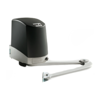
Where possible, it is advisable to install mechanical
stops on the ground for a good functioning of the
operator
2x1,5
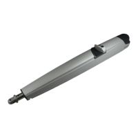
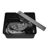
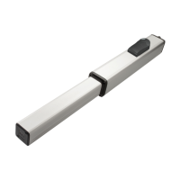
MAIN PARTS
Covering lid for terminal board
Rear fixing bracket
Cable glands
Front
fixing
bracket
Manual release
Lock nut
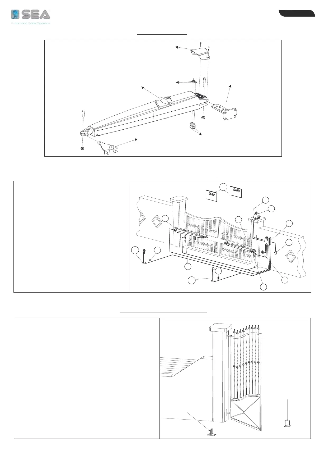
EXIT
ENTRY
STANDARD INSTALLATION
1) Operator
2) Mechanical stop
3) Electronic control unit
4) Flashing lamp
5) Right Photocell (Dx)
6) Differential switch 16A - 0,03A
7) Left Photocell (Sx)
8) Start/Stop push button with key
9) Antenna
10) Support for photocells
11) Warning notice
Mechanical
stop
in closing
Mechanical
stop
in opening
GATE ARRANGEMENT
ENGLISH
International registered trademark n. 804888