16
INTERNAL METAL RELEASE SYSTEM
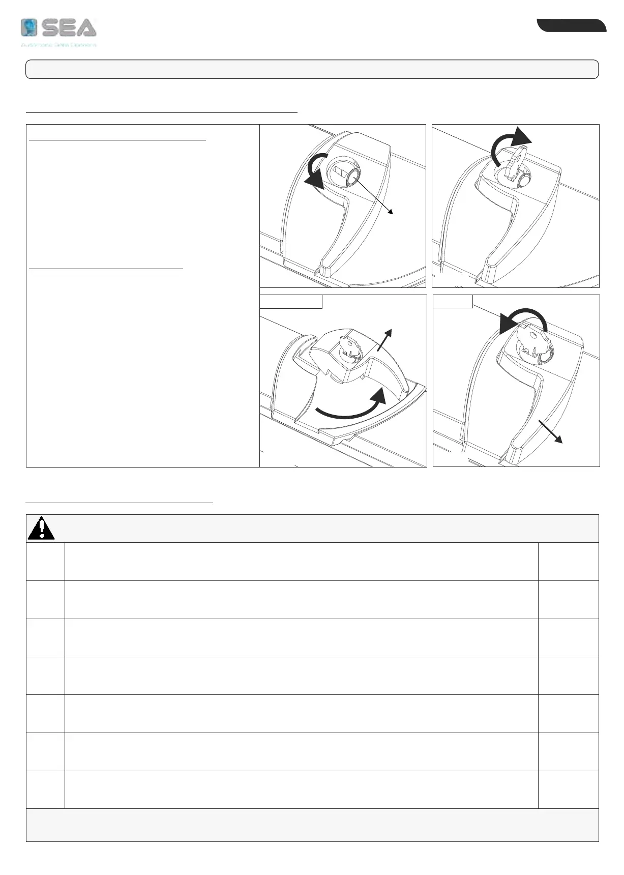
TO RELEASE THE OPERATOR:
1) Turn counter-clockwise the lock
protection cover (Fig. 22)
2) Insert the key and turn of about 90°
clockwise (Fig. 23)
3) handleTurn the counter-clockwise to
release the operator (Fig. 24)
TO LOCK THE OPERATOR:
1) Turn the handle clockwise to revert it to
the initial position
2) Turn the key about 90° counter-
clockwise (Fig. 25)
3) After having relocked the operator, close
the lock protection cover to prevent
damages due to atmospheric agents
NOTE: for a proper operation of the
manual release it is recommended to
observe the current regulations
regarding the thrust force
90°
90°
Fig. 25
LOCK
RELEASE
Fig. 22
Fig. 23
Fig. 24
PERIODIC MAINTENANCE
TO THE ATTENTION OF THE TECHNICIAN AND THE END-USER
Handle
Handle
Lock
protection
cover
1
2
3
4
5
6
7
ALL OPERATIONS MUST BE MADE EXCLUSIVELY BY AN AUTHORIZED INSTALLER AND WHEN POWER SUPPLY IS OFF
AFTER THE PERIODICAL MAINTENANCE OPERATIONS IT IS NECESSARY TO REPEAT THE TEST OF THE
AUTOMATION AND ITS COMMISSIONING
YEARLY
YEARLY
YEARLY
YEARLY
YEARLY
YEARLY
YEARLY
Check the robustness and the stability of the gate, especially of the points of support
and/or the gate points of rotation (pivots)
Check the release system function
Check and grease the fixing pivots and the endless screw
Check the integrity of the connection cables
Verify the function and the conditions of the mechanical stops in opening and closing
Verify the good condition of all mechanism subject to stress
(as front and rear fixing brackets)
Check the function of all accessories, in particular of all safety devices
ENGLISH
International registered trademark n. 804888