15
Fig. 18 Fig. 20
Fig. 19
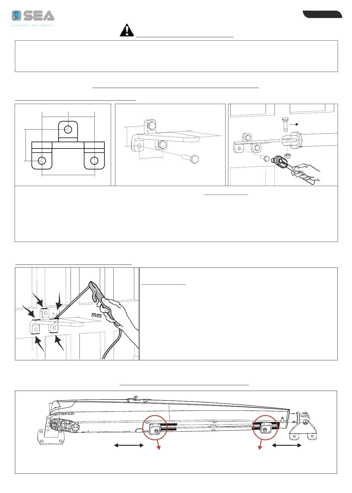
110 mm
62 mm
38mm
62mm
= =
38mm
(A)
Once the operator has been mounted on the rear fixing bracket,
close the leaf and proceed as follows:
1) Release the operator keeping it always in a horizontal position
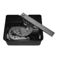
2) Weld the front fixing bracket on the gate operating on the points
indicated by the arrows (Fig. 21)
3) Insert the bracket into the housing pin on the operator (Fig. 20)
and tighten the «A» screw to max 8.5 Nm
CAUTION: Lubricate the pin with grease before installing the
front fixing bracket on the operator
1 - According to the gate type (wood, iron, aluminium) the front bracket can be welded or screwed
2 - Before mounting the rear and the front fixing brackets, lubricate with water repellent grease
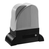
3 - The operator must be mounted with the release facing upwards (Fig. 14)
PRELIMINARY NOTES
FRONT FIXING BRACKET MOUNTING
SCREWED FRONT FIXING BRACKET
WELDED FRONT FIXING BRACKET
Once the operator has been mounted on the rear fixing bracket, close the leaf and proceed as follows:
1) Release the operator keeping it always in a horizontal position
2) Screw the front fixing bracket onto the gate in correspondence of the holes made respecting the
dimensions as per Fig. 18 and Fig. 19
3) Insert the bracket into the housing pin on the operator (Fig. 20) and tighten the «A» screw to max 8.5 Nm
CAUTION: Lubricate the pin with grease before installing the front fixing bracket on the operator
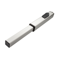
LIMIT SWITCH
IN CLOSING
30 mm
Max
1
10 mm
Fig. 21
MAGNETIC LIMIT SWITCHES
LIMIT SWITCH
IN OPENING
55 mm
Max
ENGLISH
International registered trademark n. 804888