2
page
3
page
INSTRUCTIONS
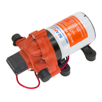
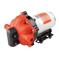
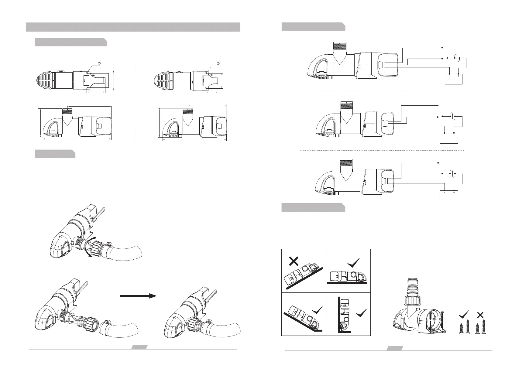
DIMENSIONAL DRAWING
130.8mm
203.4mm
84.3mm
14A
55.07mm
56.28mm
43.2mm
2- 4.3
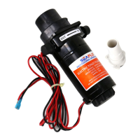
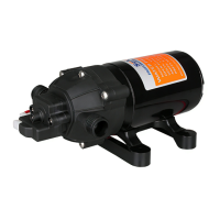
14B/14C
111.8mm
183.4mm
84.3mm
43.2mm
35.1mm
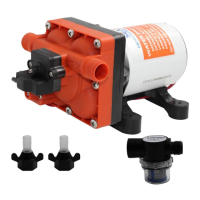
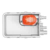
PLUMPING
The fittings are designed as a split quick connect joint, which adopts the split design of lock nut and hose
barb connector. This solution can quickly disassemble and replace the fitting without dismantling the water
pipe. Hose barb straight fittings and hose barb elbow fitting can meet the needs of most users. The lock nut
is universal.
Demolition process of split quick connect fittings: Disassemble the lock nut --> Completed
Water pipe and Hose barb fitting installation process:
2- 4.3
WIRING DIAGRAMS
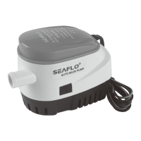
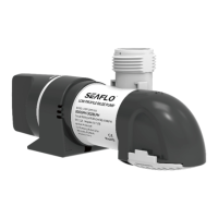
INSTALLATION
We recommend using #8 Stainless Steel screws of an adequate length as to secure the pump but not
penetrate the entire thickness of the hull. Use a flexible sealant in the screw holes to prevent water from
penetrating the screw holes.
Mounting Directions:
Screws:
The installation method is as shown on the left:
First remove the motor assembly; Second
install 2*M4 screws on the base; Third install
the motor assembly.
Fuse
Black wire - negative pole
Battery
14A
Brown wire
Manual mode
Brown&white wire
Automatic mode
Fuse
Black wire - negative pole
14B
Brown wire
Manual mode
Brown&white wire
Automatic mode
Battery
14C
Fuse
Black wire - negative pole
Brown wire - positive pole
Battery