Seagate Nytro 2.5” x 7mm SSD Product Manual, Rev. A 8
Scope
www.seagate.com
NOTE You can find a description of sub-system management data to the host over the
SMBus interface in the NVM Expresss Management Interface 1.0.
1.6.1 Vital Product Data (VPD)
The drives access a Vital Product Data (VPD) EEPROM page as listed below through address 0xA6.
This requires 3.3V Auxiliary voltage.
NOTE
Initial and Maximum Power requirements are not supported.
8
08
Length of identification: Indicates number of additional bytes to read before encountering PEC.
This value should always be 22 (16h) in implementations of this version of the spec.
10 : 09
Vendor ID: The 2 byte vendor ID, assigned by the PCI SIG. Should match VID in the Identify Controller command
response. MSB is transmitted first.
30 : 11
Serial Number: 20 characters that match the serial number in the NVMe Identify Controller command response.
First character is transmitted first.
31
PEC: An 8 bit CRC calculated over the slave address, command code, second slave address and returned data.
Algorithm is in SMBus Specifications.
32+ 255 : 32
Vendor Specific: This data structure shall not exceed the maximum read length of 255 specified in the SMBus
version 3 specification. Preferably length is not greater than 32 for compatibility with SMBus 2.0, additional blocks
shall be on 8 byte boundaries.
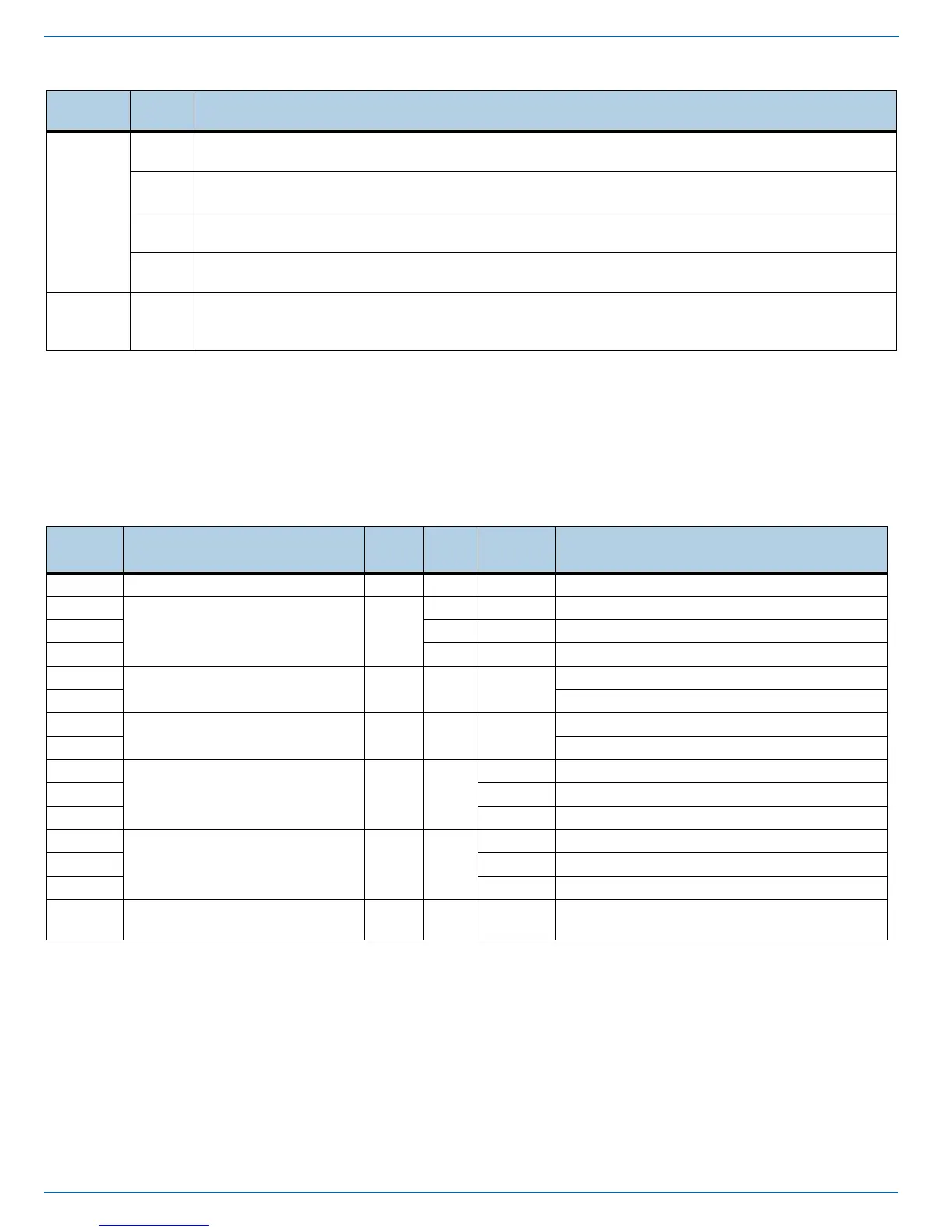
Table 6 VPD Structure
Address Function Type
Size
(B)
Default
Size
Description
0 Class Code RO 3 Vendor Device type and programming interface
3
ID RO
2 Vendor PCI-SIG Vendor ID
5 20 Vendor Serial Number (vendor unique)
25 40 Vendor Model Number (ASCII string)
65
PCIe Port 0 Capabilities RO 2 Vendor
Maximum Link Speed
66 Maximum Link Width
67
PCIe Port 1 Capabilities RO 2 Vendor
Maximum Link Speed
68 Maximum Link Width
69
Initial Power Requirements RO 3
Vendor 12V power rail initial power requirement (W)
70 0 Reserved
71 0 Reserved
72
Maximum Power Requirements RO 3
Vendor 12V power rail initial power requirement (W)
73 0 Reserved
74 0 Reserved
75
Capability List Pointer RO 2 Vendor
16-bit address pointer to start of capability
list (zero means no capability list)
Table 5 Out of Band Management (SMBus) Protocol (continued)
Command
Code
Offset
(byte)
Description