The maximllm permiued ripple is 1000V (peak-to-peak) on either
+ 12Volts or +,Volts measured on Ihe hoSlsystem power supply across
the following equivalent resistive loads:
-+- 12 Volts DC 1612
+ S Volts DC SQ
Power may be applied or removed in any sequence without
~=of
data or damage to the drive.
+ U Volls DC:
Voltage Tole:rance (including ripple):
Maximum elmeR!
Oil Power-on:
Typical Current
+5 Volts DC:
Voltage Tolerance (inc. ripple):
Typical Current:
Power
This element changes raw digital data to a differential data. providins
immunity to common mode noise during transmission.
This element detects bit positions as the slope of the Read Data signals
crosses the zero threshold. At this point analog data an: cbanged to di· .
gig).
1.2.ti\
7.2.1
7.2.'
ZERO-CROSS DETECTOR
TIME DOMAIN FILTER
LINE DRIVER
When a high resolution head reads a low frequency data pallem, there
is
I tendency for the head signal to decay between bilS. If the signal de·
cays below the uro cross threshold. a spurious data bit will be generat-
ed. Such false bits are ignored by delaying the clocking bit past the p0-
tentia! point of highest drop.
""
INPUT NOISE RIPPLE
±S%
2.2 Amp
.9 Amp
1: ,1ft
.gAmp
14.8 typical'
1.11.1
1.11.2 INPUT NOISE FREQUENCY
20MHz max. on both the + 12 and + S Volt lines
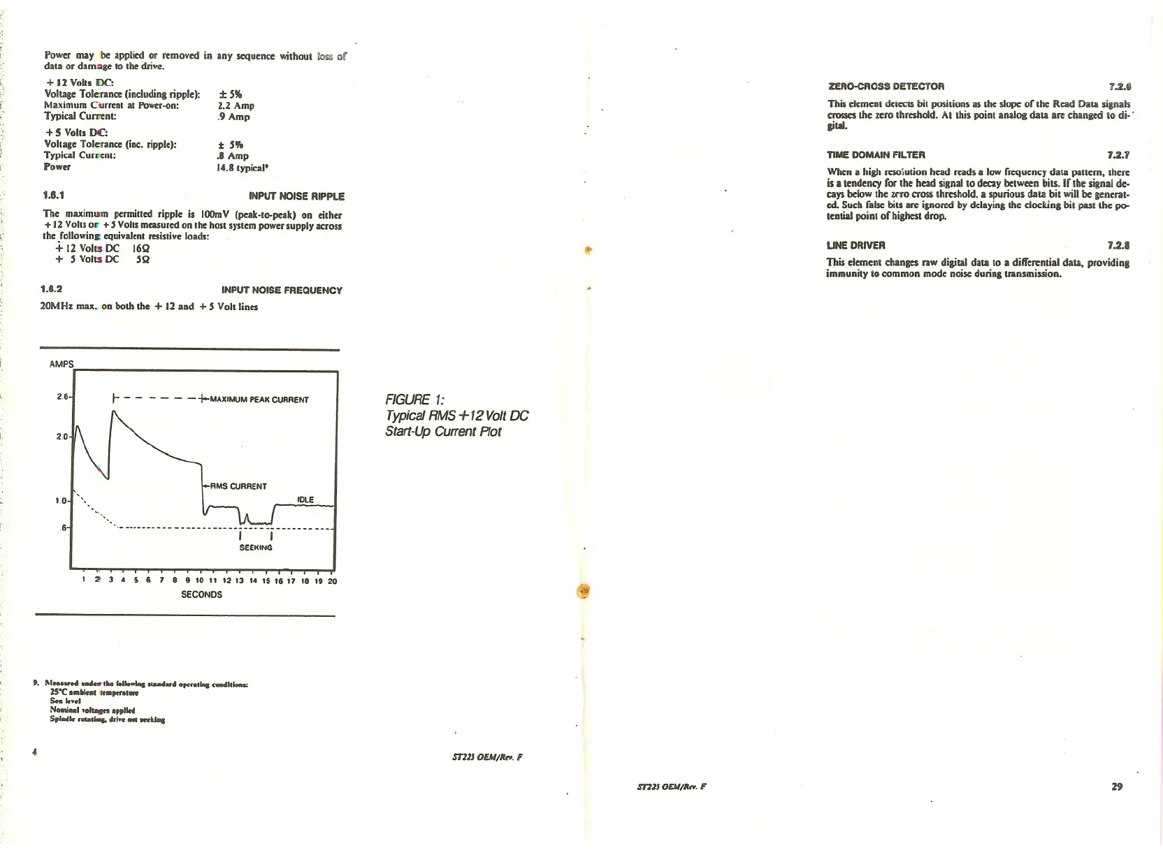
AMPS
26
2.0
1.0
6
r-- -- - -+-MAXIMUM PEAK CURRENT
IDlE
I I
SEEKING
FIGURE 1:
Typical RMS +12Volt DC
Start-Up CUffent Plot
1 ~ 3 4 5 6 7 8 9 10 11 12 13 14 15 18 17 18 19 20
SECONDS $
t. 1\1•••••••• ....." 1M 101••••••••••••••••••••• '•••• coMl,"'"
JS"C ••• _
1••.,.,.1_
s.. .....
NotnI•• 1.",,- .,,1'"
SpI•••••••••••••••n•• III -kilt
4
ST11J OEM/RIO. F
ST11J OU//hY. F 29