O~'~-..'.O£l'· .•••.· •.~ •. ~••••• "'"_ ••__ •••.• ' .•• _ •.•••.••.••..
7.2
READ OPERATION
FIGURE 23:
Read Operation
9)
.-·0
"'II
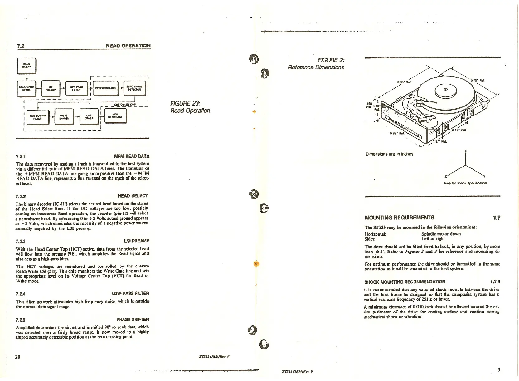
FIGURE 2:
Reference Dimensions
The data recovered by reading a track is transmitted to the host system
via a differential pair of MFM READ DATA lines. The transition of
the
+MFM READ DATA line going more positive than the - MFM
READ DATA line. represents a nux reversal on the tfilck of the select·
ed head.
The binary decoder (IC 4H) selects the desired head based on the status
or the Head Select lines. If the DC vollases are too low, possibly
causing an inaccurate Read operation, the decoder (pin.J2) will select
a nonexistent head. By rererencing 0 to + 5 Volts actual ground appears
as - 5 Volls, which eliminates the necessity of a negative power source
normally required by the LSI preamp.
With the Head Center Tap (HCT) active. data from the selected head
will now into the preamp (9E). which amplifies the Read signal and
also acts as a high-pass filler.
The HCT voltages are monitored and controlled by the custom
Read/Write LSI (SH). This chip monitors the Write Gate line and sets
the appropriate level on its Voltage Center Tap (VeT) for Read or
Write mode.
The ST22S may be mounted in the following orientations:
Horizontal: Spindle motor dowo
Sides: Left or riaht
The drive should not be tilted front
10 back. in any position, by more
thail
±5'. Refa to Figures 2 and J for reference and mounung di·
mensions.
for optimum performance the drive should be formatted in the Slime
orientation liSit will be mounted in the bost system.
1.7
1.7.1
A.is lor Shock speUfication
,A
y
Dimensions are in inche'i.
MOUNTING REQUIREMENTS
SHOCK MOUNTING RECOMMENDATION
~
;»
"
LSI PREAMP
HEAD SELECT
MFM READ DATA
1.2.1
1.2.3
1.2.2
This filter network attenuates high frequency noise. which is outside
the normal data sipal range.
Amplified data enters the circuit and is shined 90' so peak data, which
was detected over a fairly broad range. is now moved to
II highly
sloped accurately detectable position at the zero crossing point.
1.2.4
1.2.5
LOW-PASS FILTER
PHASE SHIFTER
o
G
It is recommended that any external shock mounts between the drive
and the host frame be designed so that the composite $yslem has
II
venicml resonant frequency of 25Hz or lower.
A minimum clearance of 0.050 inch :shouldIx: allowed mround die cn·
ure perimetCl' of the drive for cooIiDi airflow and mo\iow during
!Mcchanicmlshock or vibration.
28
ST1110EM/I'. ••.
If
.,.. .•.-..•. _,-----_.~~.-----~~.--..
STl13 OEM/~rI.F
,