A Write sequence is initiated when Write Gate is activated. which
causes the Read/Write LSlto apply
+ 12 Volls 10 the center tap or the
selected lead; concurrently data is sent
10 the line receiver.
WRITE DATA is trans!11ined by a differential pair which defines the
transitions
10 be wriUen on Ihe disc. The + MFM WRITE DATA iille
aoing more: posilive than the - MFM WRITE DATA line is Iile active
Iransition. Tilis siBlIalmust be do"en to aninaclive Slale wilen in Ihe
Read mode.
Differenlial Write flata. which is precompensated MFM. is received
rrom the controller.and changed
10 sinBie line. II is then red into the
pulse generator. which changes pulse data to square wave data.
Pin·S. at IC SH. will be activated ir plus data is to be wrillen. Pin-9
will be activated ror minus data,
U.2 HANDUNGAND STATIC-DISCHARGEPRECAUTIONS
After unpacki!1B and prior to system integration, the drive is eAposed
to potential ha ndling and ESD hazard.
De DOt touch the PCB "l~nKton, boIlEd rompoMnts or the
printed drcult. cable _Itbout obser.lnl Slatlc-dlscharae precautions.
Handle tbe drin b)' tbe (rame onl)'.
II is stronBly recommended that the drive always rest on a padded sur.
race, with the l1eads parked over the shippinB zone, until the drive is
mounted in the host system.
1.1.3 SHIPPINGZONE
The ST22S employs a shippinB lone. located rrom Cylinders 61S to
670, to preserve data integrity during shippin8ltranspon. The
Read/Write heads may be parked in the shipping zone by issuing a
seek to any cylinder between 615-670. The drive may then be
powered-down.
Upon power-up. the drive will recalibrate to Track _. Ir the heads are
parked while power is still applied. any Step pulse will cause the unit
to recaJibrate to Track ~.
~
;'!
MFM WRITE DATA
WRITE GATE
LINE RECEIVER
1.1.1
1.1.2
7.1.3
1------- 100",-, - 1
~i J 'm~21 .... _~--:-r
UN t O~ - "3 moll
~.,'~ ,,~. _' u~ I
T f, L;II. 02 ,
021 02 . e•• ' t .51) "t 02
,": SII I I ' 12'''' t $1.
1 ~ -1. MIIl"lI'G
• 17 t: a:z 3." t 01 '·uou:.~ .•~ tIpe.
fCSO t 5" (1125 t: 51' / '0fIII. ~ Oft ca"h udr;
"UUSC·18t1:!XI
'....,.--:r- I 1/
'"I I ,
5G'S t 010
Ct., 22!: asl
,
!
,
f 550t02
rT'
o
o
Oi.
·
·
·
D
$ 7$':
(, .•• os-:!}
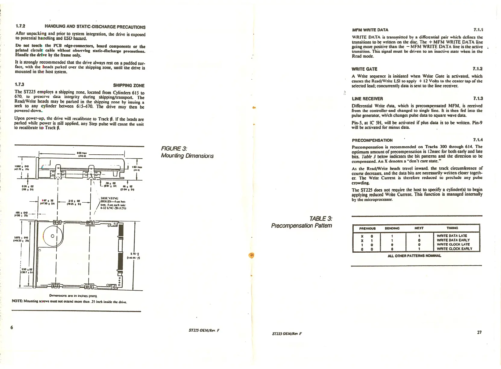
FIGURE 3:
Mounting Dimensions
$
TABLE 3:
Precompensation Pattern
PRECOMPENSATION 7.1.4
Precompensation is recommended on Tracks 300 through 614. The
optimum amouill or precompensalion is 12nsec ror both early and late
bits. Tablt
J below indicates the bit panerns and the direction 10 be
compensated. An X denotes a "don't care state."
As the Read/Write heads travel inward. the track circumrerence or
course decreases. and the data bits are necessarily written eloser togeth.
er. The Write Current is Iherefore reduced
10 preclude any pulse
crowding.
The ST22S does not require the host to speciry a cylinderis) to beJin
applying reduced Write Currenl. This runction is managed internally
by the microprocessor •
PREVIOUS
IENOIHG
NEXT
TIMING
X
0
t
t
WRITE DATA LATE
X
t t 0WRITE DATA EARLY
t
0 0 0
WRITE CLOCK LATE
0
0 0 t
WRITE ClOCK EARLY
ALL OTHER PATTERNS-.u.
Donw1soons are in inches (mml.
NOn:: Mountin, JCIrtWI mIlS! •••••••••• more .lIon .2' inch inside .he drive.
6
STll' OEMIR,.. F
srl1' OEMIR". F
27
 Loading...


