This section details Ihe physical specificalions or the host/drive inti:1l-
face mnnecto", Conneclor dimensions and iJili IIIS5isnmeniSfollow
under IUIchsection. Refer
10 Figure 9 for all overall view of the drive
and the interface connectors.
Two pain of balanced sisnals are employed for data transfer: MfM
WRITE DATA and MFM READ DATA. Data lransfer lines belween
Ihe hosl syslem and Ihe drive are dilferenlial in nalure and may nol
be multiplexed. Refer above
10 TaM" 1 for data lransfer pin assign-
ments and
Figr"t' 7 for a hosl/drive interconnection example.
1.0
DATA TRANSFER
LINES
2.0
ST225
HOST/DRIVE
INTERFACE
CONTROllST ATUS SIGNALS
PCB EDGE-CONNECTOR, J1
2.1
i'
HIGH
TRUf
7.1
FlAT CABI.£ OR TWlSTEO PAIR
HIGH
'TRUE
WRITE OPERA nON
FIGURE 21:
Data Signal
Driver/Receiver
Combination
""
Do IICri tOiiCh the PCB edge-coniiedon, board componeob or the
printed circuit albie, wllhout o~IDI !ltadc-dlscharae precaudoliS.
"melle the drive by the frame
001)'.
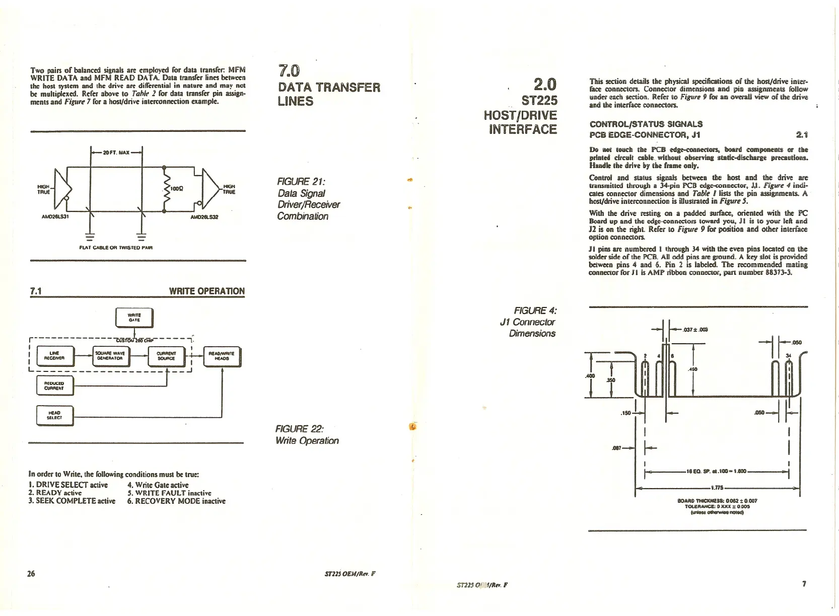
Control and status signals belween the host and the drive are
lransmined through a 34-pin PCB edg«onneclor, J,I.
Figurt <Iindi-
cales connector dimensions and Table I list! Ihe pin assignments. A
hosl/drive interconnection is illustrated in
Figure 5.
With the drive resting on a padded surface, orienled wilh the PC
Board up and Ihe edge-coonectors toward you, J I is 10 your lefland
J2 is on the right Refer to Figure 9 for position and other interface
option connectors.
11 pins are numbered I through 34 with the even pins located on the
solder side of the PCB. All odd pins are ground. A key slOI is provided
belween pins 4 and 6. Pin 2 is labeled. The recommended mating
connector for JI is AMP ribbon connector, part number 88373-3.
FIGURE 22:
Write Operation
Wi'
FIGURE 4:
Jl Connector
Dimensions
.017
-i
I
~
II:'~
In order to Wrile, Ihe following condilions must be lrue:
I. DRIVE SELECT active 4. Wrile Gale active
2. READY active 5. WRITE FAULT inactive
3. SEEK COMPLETE active 6. RECOVERY MODE inactive
26 STl1j DEM/R,.,. F
ST113 O';:;I/R,.,. F
t-
18 EO. SP." .100- 1.800
I,n5
IIOA~O THICXNII!U:0.082 ~ 0.007
TOUluua: 0 xxx :>: 0.005
__ -.ell
"i
7