Barracuda 18XL Product Manual, Rev. A 23
6.2.3 Current profile
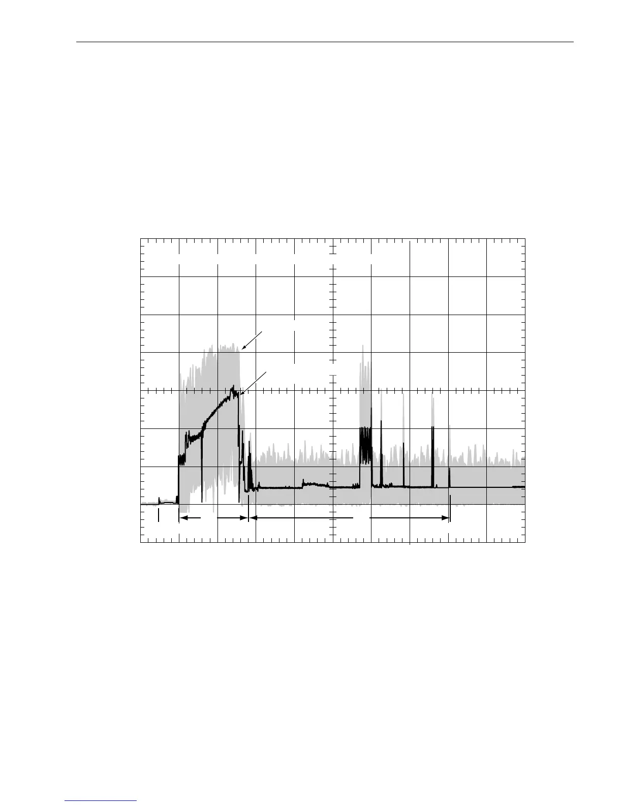
Figures 3a and 3b identify the drive +5 V and +12 V current profile. The current during the various times is as
shown:
Note.
All times and currents are typical. See Table 2 for maximum current requirements.
Figure 3a. Typical Barracuda 18XL family drive +12 V current profile
T - Power is applied to the drive.
T1 - Controller self tests are performed.
T2 - Spindle begins to accelerate under current limiting after performing drive internal
diagnostics. See Note 1 of Table 2.
T3 - The heads move from the landing zone to the data area.
T4 - The adaptive servo calibration sequence is performed.
T5 - Calibration is complete and the drive is ready for reading and writing.
0.0 2 4 6 8 10 12 14 16 18 20
0.0
0.5
1.0
1.5
2.0
2.5
3.0
A
Seconds
T1 T3
AC Envelope
T2
Nominal (average)
DC curve
+12 Volt Current during spindle start – Typical Amperes
T
T4
T5