Barracuda 18XL Product Manual, Rev. A vii
List of Figures
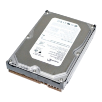
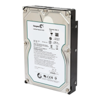
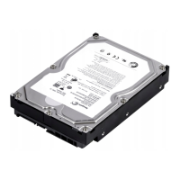
Figure 1. Barracuda 18XL family drive (model “LC” version with 80-pin SCSI I/O connector shown). . . 1
Figure 2. Barracuda 18XL family drive . . . . . . . . . . . . . . . . . . . . . . . . . . . . . . . . . . . . . . . . . . . . . . . . . . 6
Figure 3a. Typical Barracuda 18XL family drive +12 V current profile . . . . . . . . . . . . . . . . . . . . . . . . . . 23
Figure 3b. Typical Barracuda 18XL family drive +5 V current profile . . . . . . . . . . . . . . . . . . . . . . . . . . . 24
Figure 3c. DC current and power vs. input/output operations per second for ST318436 drives
(LVD only) . . . . . . . . . . . . . . . . . . . . . . . . . . . . . . . . . . . . . . . . . . . . . . . . . . . . . . . . . . . . . . . 25
Figure 3d. DC current and power vs. input/output operations per second for ST39236 drives
(SE only). . . . . . . . . . . . . . . . . . . . . . . . . . . . . . . . . . . . . . . . . . . . . . . . . . . . . . . . . . . . . . . . . 25
Figure 4. Locations of PCBA components listed in Table 3 . . . . . . . . . . . . . . . . . . . . . . . . . . . . . . . . . 27
Figure 5. Recommended mounting . . . . . . . . . . . . . . . . . . . . . . . . . . . . . . . . . . . . . . . . . . . . . . . . . . . . 29
Figure 6a. Mounting configuration dimensions for “W,” “LW,” and “LWV” model . . . . . . . . . . . . . . . . . . 31
Figure 6b. Mounting configuration dimensions for “LC” and “LCV” model . . . . . . . . . . . . . . . . . . . . . . . 32
Figure 6c. Mounting configuration dimensions for “N” models . . . . . . . . . . . . . . . . . . . . . . . . . . . . . . . . 33
Figure 7a. Barracuda 18XL family drive ID select (W/LW/LC/LWV/LCV models). . . . . . . . . . . . . . . . . . 38
Figure 7b. Barracuda 18XL family drive ID select header J6 for N model (J6 Pins 1–12) . . . . . . . . . . . 39
Figure 7c. Barracuda 18XL family drive ID select header J5 for W/LW/LWV models (J5 Pins 1–12). . . 40
Figure 7d. Barracuda 18XL family drive option select header (for LW/LC/LWV/LCV models) . . . . . . . . 41
Figure 7e. Barracuda 18XL family drive option select header (for N and W models) . . . . . . . . . . . . . . . 41
Figure 8. Air flow (suggested) . . . . . . . . . . . . . . . . . . . . . . . . . . . . . . . . . . . . . . . . . . . . . . . . . . . . . . . . 43
Figure 9a. Model “LW” and “LWV” drive physical interface (68 pin J1 SCSI I/O connector). . . . . . . . . . 62
Figure 9b. Model “LC” and “LCV” drive physical interface (80 pin J1 SCSI I/O connector and
DC power connector) . . . . . . . . . . . . . . . . . . . . . . . . . . . . . . . . . . . . . . . . . . . . . . . . . . . . . . . 62
Figure 9c. Models “N” and “W” drive physical interface . . . . . . . . . . . . . . . . . . . . . . . . . . . . . . . . . . . . . 63
Figure 10a. SCSI daisy chain interface cabling for “LW” model drives . . . . . . . . . . . . . . . . . . . . . . . . . . . 67
Figure 10b. SCSI daisy-chain interface cabling for “N” and “W” model drives . . . . . . . . . . . . . . . . . . . . . 68
Figure 11a. Nonshielded 68-pin SCSI device connector used on “LW” models . . . . . . . . . . . . . . . . . . . . 69
Figure 11b. Nonshielded 80 pin SCSI “SCA-2” connector, used on “LC” models. . . . . . . . . . . . . . . . . . . 70
Figure 11c. Nonshielded 50-pin connector for “N” and “W” models . . . . . . . . . . . . . . . . . . . . . . . . . . . . . 71
Figure 12. Single-ended transmitters and receivers on “N” and “W” models . . . . . . . . . . . . . . . . . . . . . 79
Figure 13. LVD steady-state output voltage test circuit (T10/1302D, Annex A, Figure 1). . . . . . . . . . . . 81
Figure 14. Typical SE-LVD alternative transmitter receiver circuits . . . . . . . . . . . . . . . . . . . . . . . . . . . . 81