INSTALLATION
MANUAL
Section 2: ELECTRICAL INSTALLATION
2.4 Operator Station
This section explains the connection between the Operator Station equipment and the Gyro Control
Box.
Reference Drawing
90310 Seakeeper 26 Gyro Cable Block Diagram
1. DETERMINE LOCATION OF OPERATOR STATION
a. The desired location of the Operator Station must be determined with respect to the
vessel arrangement.
b. The operator display should be located on the bridge console.
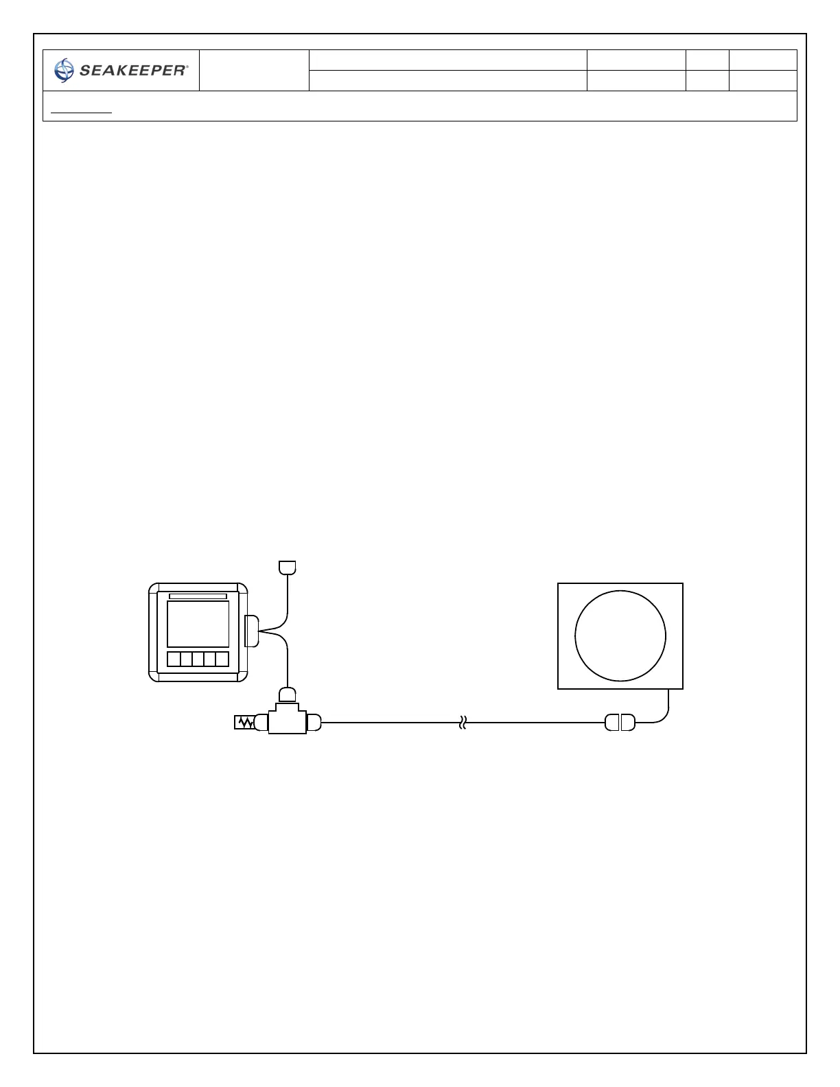
c. Figure 10 below shows the CANbus communications link for the Operator Station. The
Terminator goes on one the far end of the Tee Adapter from the Gyro.
FIGURE 10 – SERIAL COMMUNICATIONS LINK FOR OPERATOR STATION
2. ROUTE SERIAL COMMUNICATIONS CABLE
a. The CAN Cable Assembly (30243, CABLE 5) is a 25 meter shielded cable and the largest
connector is a molded plug with maximum outer diameter of .58 inch (14.8mm).
b. CABLE 5 must be routed and installed in the vessel from the Gyro (female end) to the
Tee Adapter (male end) at the Operator Station.
CAN CABLE ASSY, 25m
SEAKEEPER
GYRO
F
F
F M
F
M
COLOR
DISPLAY
F
M
"SHIP MONITOR"
F
DISPLAY
INTERFACE
CABLE
TEE
ADAPTER
TERMINATOR,
FEMALE
M
"GYRO"
 Loading...