OPERATION
MANUAL
Section 1: SYSTEM OVERVIEW
1.1 Gyro Assembly
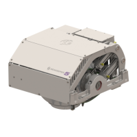
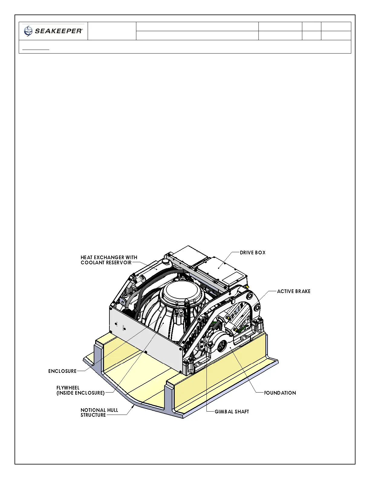
The gyro assembly consists of a flywheel housed in a cast aluminum vacuum-tight enclosure. The
flywheel spins about a vertical axis and is supported by upper and lower pairs of bearings. A DC
brushless motor mounted inside the enclosure spins the flywheel at high speed.
The enclosure is fastened to two gimbal shafts that are supported by gimbal bearings on either side.
These shafts establish an athwartship gimbal axis about which the flywheel and enclosure precess or
rotate up to +/- 70 degrees during operation. The gimbal bearings are supported by a foundation which
is attached to the hull structure. This foundation transfers the loads that the gyro produces to the hull
structure.
An active hydraulic brake mechanism is located on the gyro assembly to regulate the gyro’s precession
motions about the gimbal shaft. It includes two hydraulic cylinders and a hydraulic manifold.
A coolant pump, heat exchanger with reservoir, and thermostat are located near the manifold. A
glycol/water mix is circulated thru a closed loop to the drive box, hydraulic manifold, and the end caps
of the enclosure to remove heat.
FIGURE 3 – GYRO ASSEMBLY