4. ASSEMBLY
4.1. FIT HANDLE: Slide handle onto top cover. Secure with screw (19), see Parts Diagram.
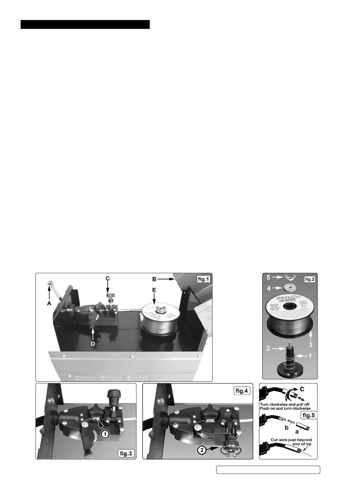
4.2. FIT COVER LOCKING SPRING: Fix Cover Locking Spring (8), see Parts Diagram, to top of front panel. Use screw, washer and spring
washer supplied. See also g.1.A.
4.3. FITTING A REEL OF WIRE
4.3.1. Depress the silver button in the front of the handle and open the top compartment. See A & B in g.1. The welder is supplied with a mini
spool containing 0.45kg of ux cored wire.
4.3.2. Referring to g.2, rotate the nut (5) anti-clockwise and remove it from the threaded spindle together with the pressure disc (4). Leave
the spring (1) on the spindle (2).
4.3.3. Place the wire reel (3) over the spindle and down onto the spring ensuring that the wire will withdraw from the spool in a forwards
direction and on the same side of the compartment as the wire feed unit.
4.3.4. Push lightly down on the top of the reel of wire and screw the pressure disc (4) onto the end of the spindle and down onto the top of the
wire reel. The reel take o pressure should be set to provide a mild braking eect to prevent overrun where loose coils of wire form on
the reel. DO NOT over tighten the pressure disc as too much braking will conict with the wire tension set on the wire drive unit.
4.3.5. Lock the position of the pressure disc by screwing the nut (5) down on top of it.
4.3.6. Referring to g.1 turn the knob on the wire lock screw (C) anti-clockwise and lift it up and away from the pressure roller moulding.
4.3.7. Swing the pressure roller moulding (D) away from the drive roller
4.3.8. Release the wire from the spool (do not allow wire to uncoil) and straighten 40-50mm of wire and gently push through the exible
plastic guide and through the 0.9mm feed roller groove (g.3.1) and into the torch liner.
4.3.9. Referring to g.4, move the pressure roller moulding back round onto the grooved drive wheel and swing down the wire lock screw to
lock it in place. See section 4.3 regarding wire tension.
4.3.10. Feeding the wire through to the torch. (See g.5) Remove gas cup (a) and contact tip (b) from end of torch as follows:
a) Take torch in left hand with the torch tip facing to the right.
b) Grasp gas cup rmly in your right hand.
c) Turn gas cup clockwise only and pull cup out to the right.
WARNING! DO NOT turn gas cup anti-clockwise, as this will damage internal spring.
d) Unscrew the copper contact tip (right hand thread) to remove.
4.3.11. Check welder is switched OFF and that the earth clamp is away from the torch tip. Connect the welder to the mains power supply and
set the voltage switch to MIN. (g.A)
4.3.12. Set the wire speed knob to position 5 or 6. Keeping the torch cable as straight as possible and press the torch switch. The wire will
feed through the torch.
4.3.13. When wire has fed through, switch welder o, unplug from mains.
a) Take torch in left hand, slide the contact tip over the wire and screw it back into place.
b) Grasp gas cup in right hand, push onto torch head and turn clockwise only.
WARNING! DO NOT turn gas cup anti-clockwise, as this will damage internal spring.
c) Cut wire so that it is just protruding from the cup.
4.4. SETTING WIRE TENSION
IMPORTANT: You must set the correct tension, too little or too much tension will cause problematic wire feed and result in a poor weld.
4.4.1. Correct tension between the rollers is checked by slowing down the wire between gloved ngers. If the pressure roller skids the
tension is correct. Try to use the lowest tension possible as too high a tension will deform the wire. When you have completed welding
allow the welder to cool before storing in a safe, dry place. Note: Damaged torches and cables are not covered under warranty.
Original Language Version
© Jack Sealey Limited
MIGHTYMIG100.V4 Issue 2 (1,6,F) 02/11/23
 Loading...