g.6
Original Language Version
© Jack Sealey Limited
MIGHTYMIG100.V4 Issue 2 (1,6,F) 02/11/23
5. WELDING PREPARATION
5.1. PREPARATION FOR WELDING
IMPORTANT! Before you commence, make sure the machine
is switched o at the mains. If welding a car, disconnect the battery
or t an electronic circuit protector. Ensure that you read, understand
and apply the safety instructions in section 1.
5.1.1. To ensure a complete circuit, the negative lead must be securely
attached to the workpiece close to the weld area. Best connection
is obtained by grinding the point of contact on the workpiece before
connecting the clamp.
5.1.2. The weld area must be free of paint, rust, grease, etc.
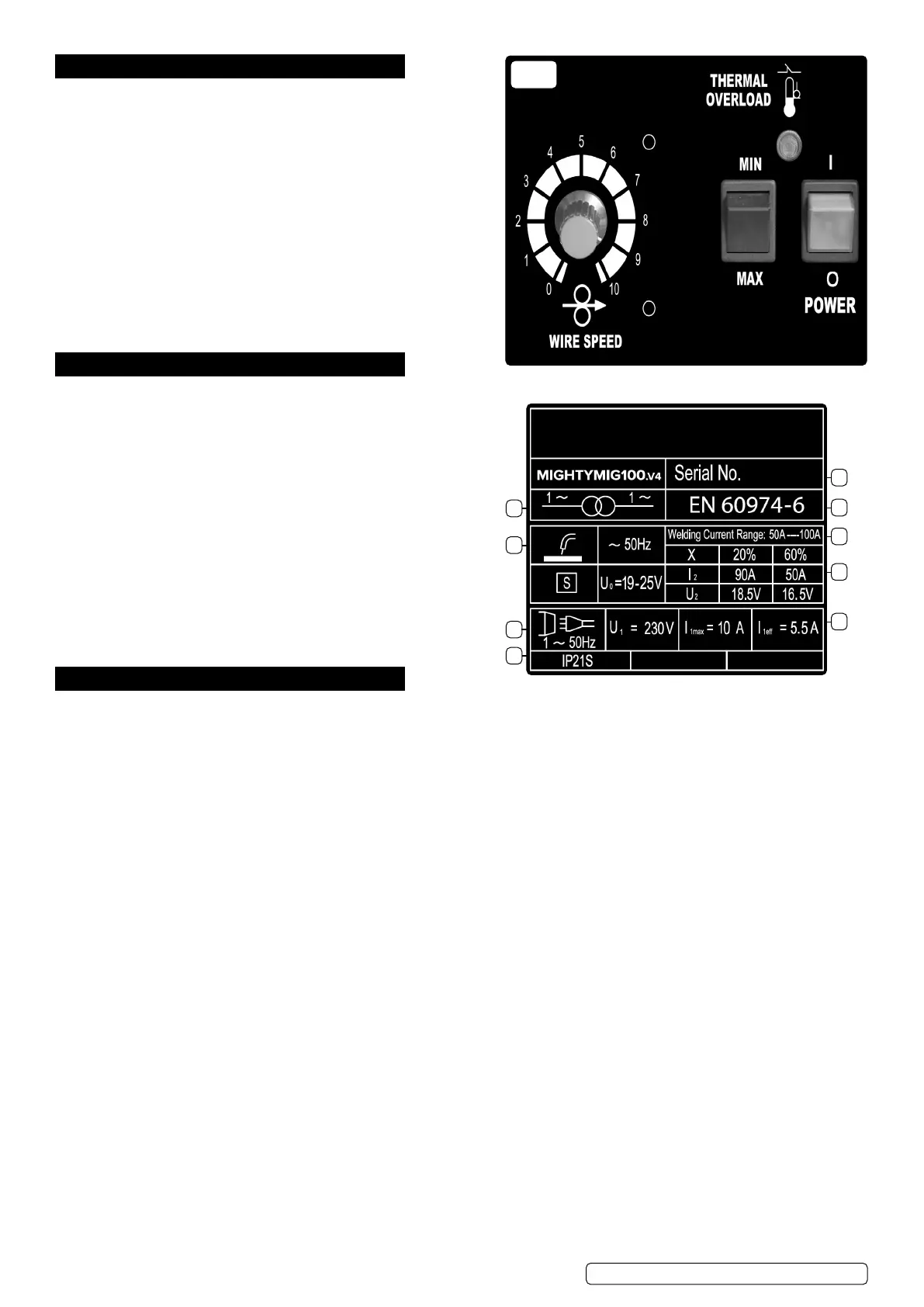
5.2. THERMAL PROTECTION, see g.6
5.2.1. Should the welder become overheated due to prolonged use beyond
the stated duty cycle the thermal protection will cause the welder to
cut out and the orange light on the front panel will illuminate. Wait
for fteen minutes for the welder to cool down at which time it will
reconnect automatically.
6. RATING PLATE
On the front panel of the welder is the ratings plate, giving the following data:
1 - The BS/EU standard relating to the safety and construction of
arc welding and associated equipment.
2 - Single phase transformer.
3 - Symbol indicates welding with a continuous ow of welding wire.
4 - Symbol for Single-phase AC supply.
5 - Rating of internal protection provided by casing.
6 - Output U0 Rated minimum and maximum no load voltage.
I2, U2 Current and corresponding voltage.
X Welding ratio based on a 10 minute cycle.
20% indicates 2 minutes welding and 8 minutes rest,
100% would indicate continuous welding.
7 - Mains Supply U1 Rated supply voltage and frequency.
I1max Maximum current.
I1e Maximum eective current.
8 - Welding current range.
9 - Serial Number. Specically identies each welder.
7. OPERATION
▲ DANGER! Unplug the welder from the mains power supply before performing maintenance or service.
7.1. WIRE FEED UNIT
7.1.1. Check the wire feed unit at regular intervals. The feed roller wire guide plays an important part in obtaining consistent results. Poor wire
feed affects the weld. Clean the rollers weekly, especially the feed roller groove, removing all dust deposits.
7.2. TORCH
7.2.1. Protect the torch cable assembly from mechanical wear. Clean the liner from the machine forwards by using compressed air. If the liner is
blocked it must be replaced.
7.3. TURNING FEED ROLLER IMPORTANT: TURN THE FEED ROLLER TO SUIT THE WIRE SIZE.
7.3.1. There are two grooves on the feed roller, 0.6mm and 0.9mm. Always have the groove that is being used on the outside of the roller
(nearest to you). To turn the feed roller first loosen the wire tension knob and move it into its up position (see fig.8-1) then move
the tensioning roller assembly to its down position (see fig.8-2). Take hold of the triangular knob on the roller retainer and rotate it
90°anticlockwise to release it as shown in fig.8.3. Now pull the roller retainer off the drive spindle to reveal the roller as shown in fig.9.
7.3.2. Pull the roller off the drive spindle, flip it over and put it back on the drive spindle. (See fig.10) The groove size you require should now be
visible on the face of the roller. Push the roller retainer back onto the drive spindle with the opening facing right. Ensure that the flanges at
the base of the retainer, seat fully into the circular recess in the main moulding and then rotate the retainer through 90° to lock it in place.
7.4. CONTACT TIP (to remove tip follow steps in 4.3.10.):
7.4.1. The contact tip is a consumable item and must be replaced when the bore becomes enlarged or oval. The contact tip MUST be kept free
from spatter.
7.5. GAS CUP (to remove cup follow steps in 4.3.10.):
7.5.1. The gas cup must also be kept clean and free from spatter. Build-up of spatter inside the gas cup can cause a short circuit at the contact
tip which will result in expensive machine repairs. To keep the contact tip free from spatter, we recommend the use of anti-spatter spray
(MIG/722308) available from your Sealey stockist.
7.6. REPLACING WIRE LINER
7.6.1. A worn or damaged wire liner will seriously affect the performance of the welder and should be immediately replaced. First wind the wire
back onto the spool and secure it. Remove the four screws securing the torch cable clamp to the wire feed unit (fig.11) and take off the
clamp.
7.6.2. Open the torch case by gripping the torch with one hand and turning the grooved ring at the base of the torch anticlockwise until it stops,
then pull it off the torch onto the torch cable. See fig.12-1.
7.6.3. Take hold of the back end of the moulding which contains the switch and pull it outwards and downwards to release it from the other
moulding as shown in fig.12.
2
3
4
5
9
1
8
6
7
 Loading...