© 2012 SeaStar Solutions Optimus Operations Manual, Rev. D
3-1
3.0 FIRST TIME OPERATION
The steering wheel is attached to this unit, which may be located
immediately under the wheel or just behind the dash panel. The
images below show typical helms.
These are supplied by the installer and may be mounted in a variety
of locations. Check near the batteries, in the circuit breaker box, or
near the PCM or hydraulic pumps. There should be a 60 amp breaker
for each PCM power feed.
3.1.2 Circuit Breakers for Optimus EPS System
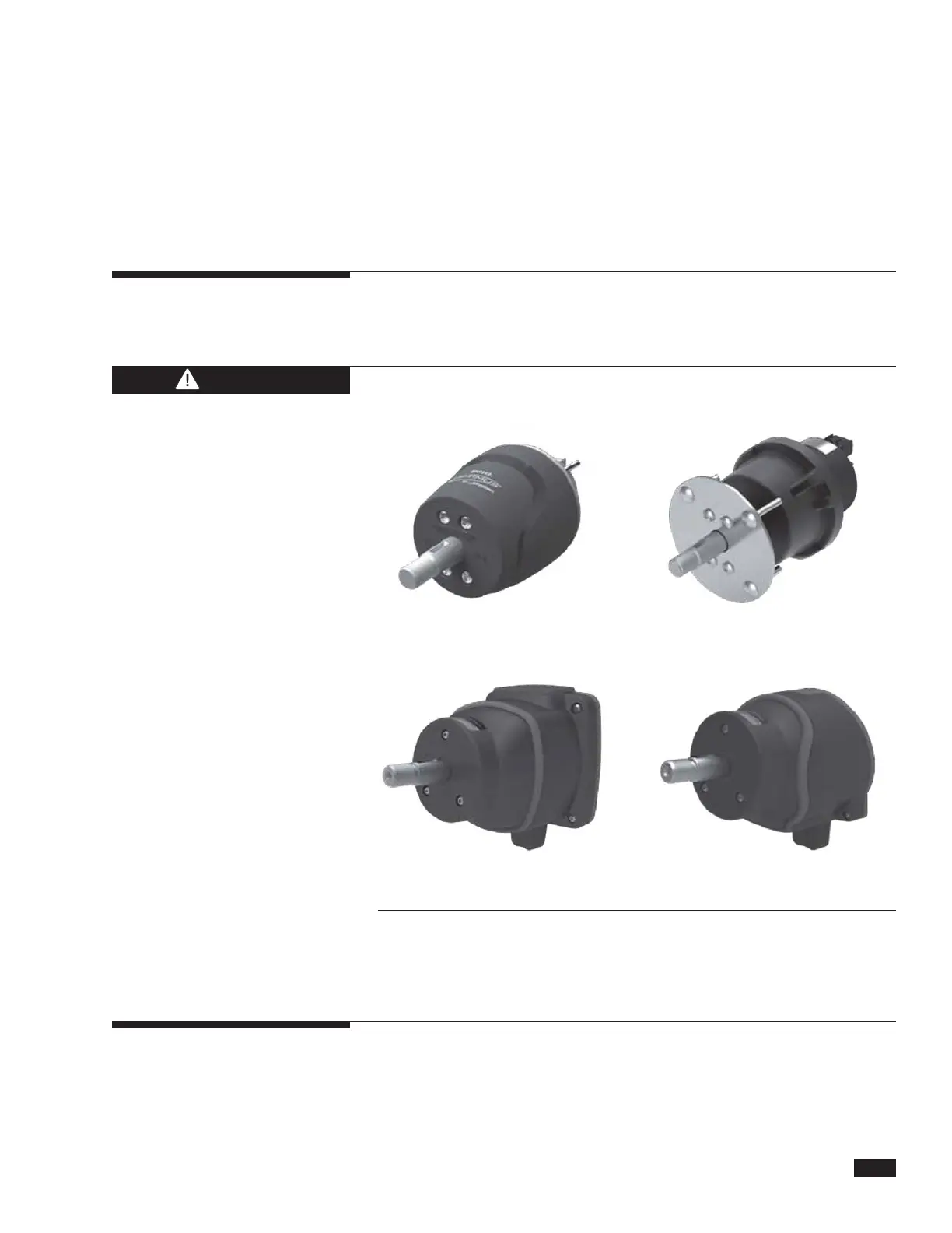
EPS Front Mount Helm
EPS Rear Mount Helm
EPS Classic Tilt Helm EPS Sport Plus Tilt Helm
3.1 Locate the Following Steering System
Components
3.1.1 Electronic Helm(s)
Figure 3-1. EPS Helm configurations.
Keep magnets away from the helm. They may interfere with proper
helm operation.
CAUTION
 Loading...