4
5
www.sebury.com.cn www.sebury.com.cn
Terminal Wire Connector 1 Function
10
Bell2
Green Not Connect
9
Bell1
White
Not Connect
8
ALARM
Grey
Alarm
7
OPEN
Yellow
6
D_IN
Brown
To Door Contact Then To Door In
5
12V
Red
4
GND
Black
(-) Negative Regulated Power Input
3
NO
Blue
Door Strike Relay N/O
2
COM
Purple
Door Strike Relay COM
1
NC
Orange
Door Strike Relay N/C
To Door Remote Control Button Then Negative
(+) 12Vdc Positive Regulated Power Input
Warning!
Do not plug adapter our transformer into mains until all wiring has
been completed and the front cover secured.
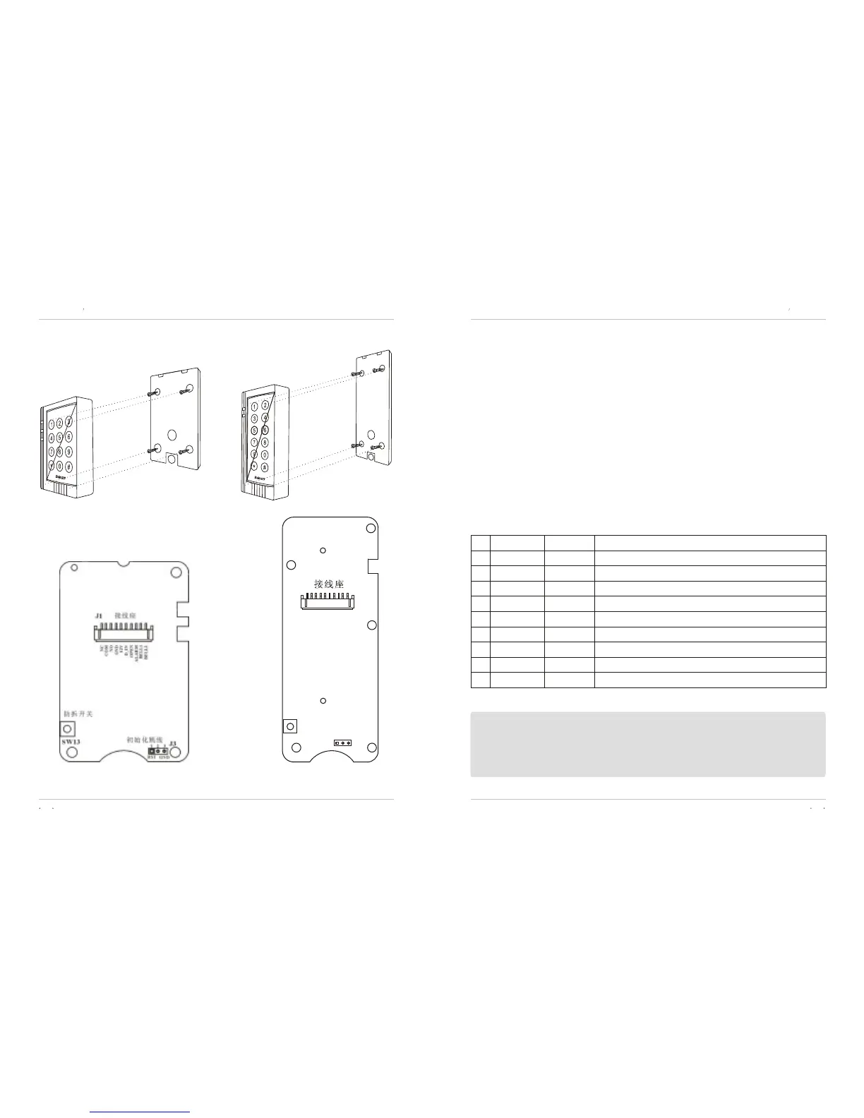
Figure 3
Wiring
Figure 4
Printed Circuit Board
K3/K4 user s manualK3/K4 user s manual
SW13
J3
RST
GND
1
2
3
NC
C
OM
NO
GND
1
2
V
_
DI
N
OPE
N
A
L
AR
M
B
E
L
L
1
B
E
L
L
2
·À²ð¿ª¹Ø
³õʼ»¯°´Å¥
J1
K4
K3
K4
K3
The front cover can be permanently secured by using the short
screw supplied K3/K4
1N4007 is necessory ,otherwise the controller doesn't work stablly.
Unplug the cable harness and connect the necessary cables,
(See Figure 5). showed as Figure 6 for special power Supply
connections, this power will make controller work stablly .
Tape any wires that are unused. Plug the cable harness , (See
Figure 5) Attach the front cover, (See Figure 3).



 To Next Page