Service Manual Replacement instructions
28.08.03/Aschke 1 30-34-00-055
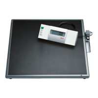
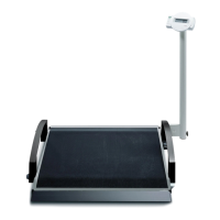
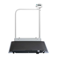
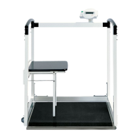
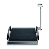
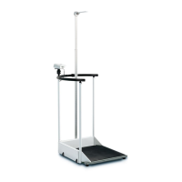
seca 634, 635
The references to pages and items relate to the replacement instructions drawing, Pages 4 – 8.
The power supply unit must not be connected.
We urgently recommend that you remove the battery pack before starting any work on the unit
(see operating instructions).
ESD protection measures must be taken whenever work is performed on electronic components.
Removal
1. Dismantling the platform (Page 4).
To remove the frame (item 4.1):
Remove the four nuts and washers (item 4.2).
To remove the insert from the platform plate (item 4.3):
Remove the nuts and washers (item 4.4).
If required: Turn off the rubber metals (item 4.5). Pay attention to the spacer sleeves (item 4.6).
If required: Remove the bow-type handle (item 4.7):
Remove the two screws (item 4.8).
If required: Remove the mat (item 4.9).
Warning: The mat will be destroyed.
Remove the residues of mat and adhesive from the platform plate (item 4.10).
Once you have removed the mat (item 4.9), you can replace the screws for the insert of the platform plate
(item 4.11) and the screws for the rubber metals (item 4.12).
2. Dismantling the frame (page 5).
Open the housing for the evaluation electronics (item 5.1). For a description refer to section 3.
Pull off the modular cable (item 5.2). For a description refer to section 3.
Remove the mains socket connection (item 5.3). For a description refer to section 4.
To remove the housing for the evaluation electronics (item 5.1):
Remove the 2 screw couplings (item 5.4).
Lift off the housing and the supporting disks (item 5.5).
To remove the holder for mains socket and bubble level (item 5.6):
Remove the 2 screw couplings (item 5.7).
Lift off the holder and the supporting disks (item 5.8).
Remove the nuts and washers (item 5.10) and remove the load cell covers (item 5.9).
Remove the nuts and washers (item 5.12) and take out the load cells (item 5.9).
Pay attention to the spacer sleeves (item 5.13).
Take out the screws (items 5.14 and 5.15).
Attention: The longer screws (item 5.14) must be reinserted at their original positions (see drawing), as
these screws are used to fix the load cell covers.
Carefully thread the load cell cable out of the frame tubes.
If required: Unscrew the adjusting feet (items 5.16 and 5.17).
3. Dismantling the housing for the evaluation electronics (page 6).
Remove the 4 screws (item 6.1) and lift off the bottom housing half (item 6.2).
Disengage the clip holder (item 6.3) and pull off the modular cable (item 6.4).
If required: Unsolder the load cell and mains socket cables from the board.
The cable gland (item 6.11) is connected with the mains cable. For a description refer to section 4.
Remove the 4 screws (item 6.5) and dismantle the remaining parts of the housing. End plates (items 6.6
and 6.7), filler pieces (item 6.8), PCB (item 6.9) and the upper half of the housing.
 Loading...