EasyManua.ls Logo

Seca 644 Series User Manual

Seca 644 Series
74 pages
To Next Page IconTo Next Page
Page #1 background imageLoading...
Page #1 background image
for seca 644, 645
Service Manual
6441321108
6441321378
6457021003
6457021193
6457021223
6457021247
6457021283
Electronic scale with standing aid, easily manoeuvrable. With NEC2 Electronic and
Turnable display and operating housing.
Valid as of: 01.02.2013
Variants:
Contents:
Description:
Service Manual Number
17-05-01-372-
When servicing or repairing seca devices according to this service manual, always take note of the
instruction manual of the product. To download the latest version of the instruction manual and EMC
Recommendation go to
www.seca.com.
Service instruction electronic 30-34-00-812 c
Cableplan
08-02-06-058 a
Replacement
30-34-00-857
Spare parts
644 1321108
Spare parts
644 1321378
Spare parts
645 7021003
Spare parts
645 7021193
Spare parts 645 7021223
Spare parts
645 7021247
Spare parts 6457021283
Spare parts drawing dispaly and assembly 30-34-00-838
Spare parts drawing baseframe
30-34-00-837
Operation mod. 644
17-10-06-382
Operation mod. 645
EMC Recommendation
17-10-07-607
30-34-00-519
Manual number: 17-05-01-372-

Table of Contents

Question and Answer IconNeed help?

Do you have a question about the Seca 644 Series and is the answer not in the manual?

Seca 644 Series Specifications

General IconGeneral
BrandSeca
Model644 Series
CategoryScales
LanguageEnglish

Summary

Electronics (NEC2) Service Instructions

1 General Information

1.1 Type Plates

Information on identifying the device via model and serial number on type plates.

1.2 Design and Function of the Scale Part

1.2.1 Design

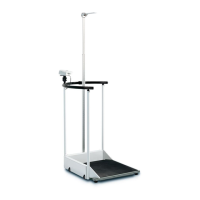
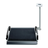
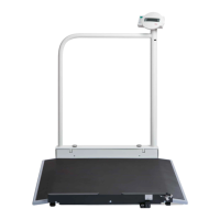
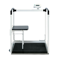
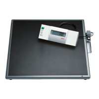
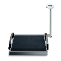
Describes the main parts of the scale, including frame, display, and power supply.

1.2.2 Function

Explains how the load cell and electronics convert force into a weight value.

1.3 Design and Function of the Head Slider

2 Maintenance

2.1 Adjustment of Scales

Details the process for adjusting the scale to compensate for measuring deviations.

2.1.1 General

2.1.2 Calibration Counter / Number of Adjustments

2.1.3 Adjustment Mode and Displaying the Calibration Counter Contents

2.1.4 Adjustment Mode and Displaying the Calibration Counter Contents [284|285]

2.1.5 Placing Adjustment Weights on the Scale

2.1.6 Example: Adjusting a Scale with 100g Graduations

2.1.7 Example: Adjusting a Baby Scale with 10g Graduations

2.1.8 Overview of Adjusting a Scale with 100g Graduations [703|704]

2.1.9 Overview of Adjusting a Baby Scale with 10g Graduations [374|376|378]

2.2 Adjusting the Head Slider [284|285]

2.2.1 Displaying the Gravity Factor

Explains how to view the gravity factor setting of the scale.

2.3 Setting the Gravity Factor [374|703|634|644|656|674|676|684|284|954]

2.3.1 Example for Gravity Factor Setting

Provides a practical example of setting the gravity factor.

2.3.2 Summary of a Typical Gravity Factor Setting Sequence [374|703]

Summarizes the sequence of actions for setting the gravity factor.

3 Errors

3.1 Error Symptoms for Scale

Lists common error symptoms for the scale and their possible causes and remedies.

3.2 Error Symptoms for Head Slider [264|274|284|285]

3.3 Radio Error Symptoms

3.4 Scale Error Messages

3.5 Head Slider Error Messages [264|274|284|285]

3.6 Radio Error Message

4 Measurements

4.1 Supply Voltage

Explains how to measure supply voltage on the electronics board to check power lines.

4.2 Load Cell

Discusses methods for identifying load cell defects using diagnosis functions or a multimeter.

4.2.1 Measurement Using a Multimeter

5 Software intended Purpose

5.1 Installation and Start

Guides through the installation and initial start-up of the 'seca wireless updater' program.

5.2 Updating the Radio Module Software

5.3 Set-up Process

5.4 Updating the Radio Module Software

5.5 Technical Requirements for Updating

5.6 Updating the Wireless Printer Software

5.7 Updating Old Printers

5.8 Problems with Updating

Cableplan

Replacement

I Safety measures

Essential safety precautions to be taken before starting any work on the scale.

II Safety instructions against electrostatic charging (ESD protection measures)

Specific precautions for handling electronic components to prevent ESD damage.

1 Baseframe

1.1 Replacing the NEC2 weight module

Step-by-step guide for removing and installing the NEC2 weight module.

1.2 Replacing the load cells

1.3 Setting the overload protection devices

2 Display

2.1 Removing the display

Details the steps to remove the printed operating and display unit.

2.2 Replacing the membrane keypad / NEC 2 display / radio module

Guide for replacing the membrane keypad, NEC2 display, or radio module.

Spare Parts List for 644 1321008 Frame

Spare Parts List for 644 1321008 Assembly

Spare Parts List for 644 1321008 Accessory

Spare Parts List for 644 1321378 Frame

Spare Parts List for 645 7021003 Frame

Spare Parts List for 645 7021193 Frame

Spare Parts List for 645 7021223 Frame

Spare Parts List for 645 7021247 Frame

Spare Parts List for 645 7021283 Frame

Spareparts drawing 644,645 assembly

Spareparts drawing 634,635,644,645 Rahmen

Related product manuals