SECTION 8 INSTALLATION AND CONNECTIONS
Doc No.: A05160691 REV Q ECO 12425 Date: 03/27/17 22
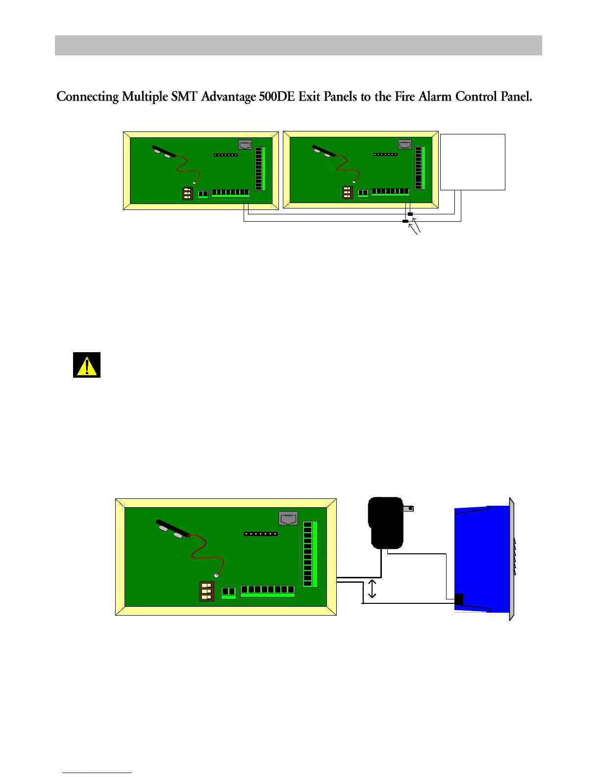
Figure 8-8 Multiple Panel and Fire Alarm Control Panel Connections
Use SCP Part # B60000438 16Awg wire for connection of the SMT Advantage 500DE Exit Panel to the fire alarm
control panel. Up to eight SMT Advantage 500DE Exit Panels can be connected in parallel to a normally open, dry
relay contact in the fire alarm control panel.
NOTE: Per NFPA-101 any locking device installed on a designated emergency
exit door must be overridden by the fire alarm control panel in case of a fire alarm
activation.
Do not connect more than eight panels in parallel to a single fire alarm relay.
Doing so could result in failure of the fire alarm release feature during a fire alarm.
Sounder Connections
Negative Lead
Positive
Lead
12 V DC
- +
EG RE SS
DO OR PU SH FIR E
PRO GR AM M ING
POR T
REC HAR G EABLE 9V NI-M H
BATTER Y ONL Y
EXTER NAL KEY PAD
O N / O FF
M U TE
HI / L O
ELE V
NU RSE
LO CK
LO CK
NO C N C
NO C N C
NO C N C
NO C N C
Figure 8-9 Sounder Connections
Connect the positive lead of the DC transformer to the positive side of the sounder. Connect the negative lead to one side of
the nurse relay. Run a jumper wire from the other side of the nurse relay to the negative side of the sounder.
Wire
Splices
Fire alarm
system.
Normally open
dry contact relay
required
1 2 V D C
- +
E G R E S S
D O O R P U S H F IR E
P R O G R AM M I N G
P O R T
R E C H AR G E A B LE 9 V N I- M H
B AT TE R Y O N L Y
E X TE R N AL K E Y P AD
O N / O F F
M U T E
H I / L O
E L EV
N U R SE
L O CK
L O CK
N O C N C
N O C N C
N O C N C
N O C N C
1 2 VD C
- +
E G R E SS
D O O R P U S H F IR E
P R O G RA M M IN G
P O R T
R E C HA R GE A BL E 9 V N I- M H
B AT TE R Y O N L Y
E X TE R N AL K E YP A D
O N / O F F
M U T E
H I / L O
E L EV
N U RS E
L O CK
L O CK
N O C N C
N O C N C
N O C N C
N O C N C


 To Next Page