Doc No.: A05160691 REV Q ECO 12425 Date: 03/27/17
Typical Installation Wiring Diagram
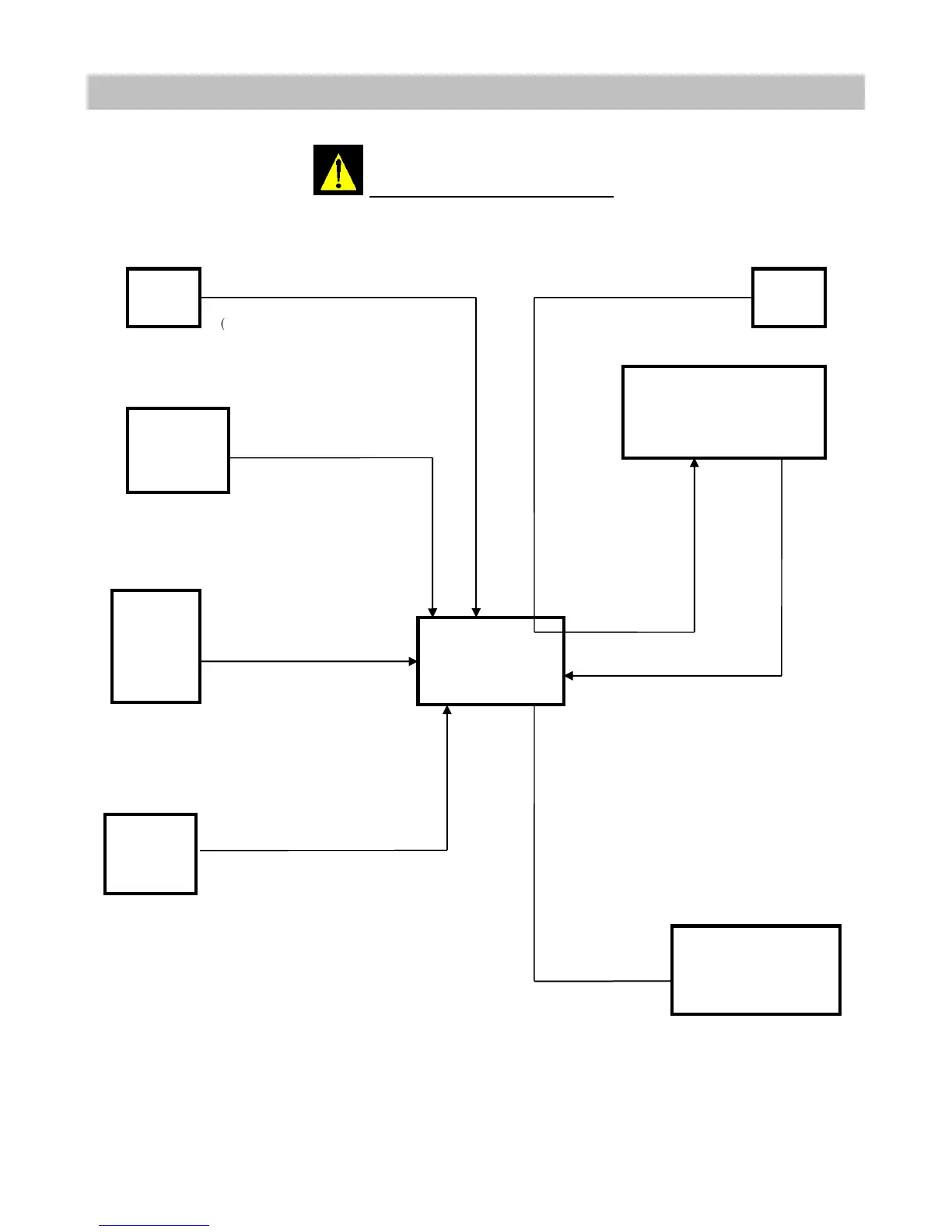
Figure 2-1 System Block Diagram
SECTION 2 SYSTEM BLOCK DIAGRAM
2 wires from Separate central or wall mount power supply
supplied to lock under 500DE control
2 wire input from door switch
2 wire input from push button
2 wire input from egress switch
2 wires from central or wall mount power
supply
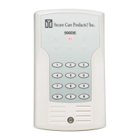
500DE
(A05160910)
Magnetic Lock with Integrated
Egress Switch
Switch
External
Keypad
Push Button
Switch
Power
Power
Nurse Station, Power
Sounder or other customer
supplied peripheral
activated by relay closure.


 To Next Page