Do not merely count the alarm input and out channel amount according to the ports
on the rear panel.
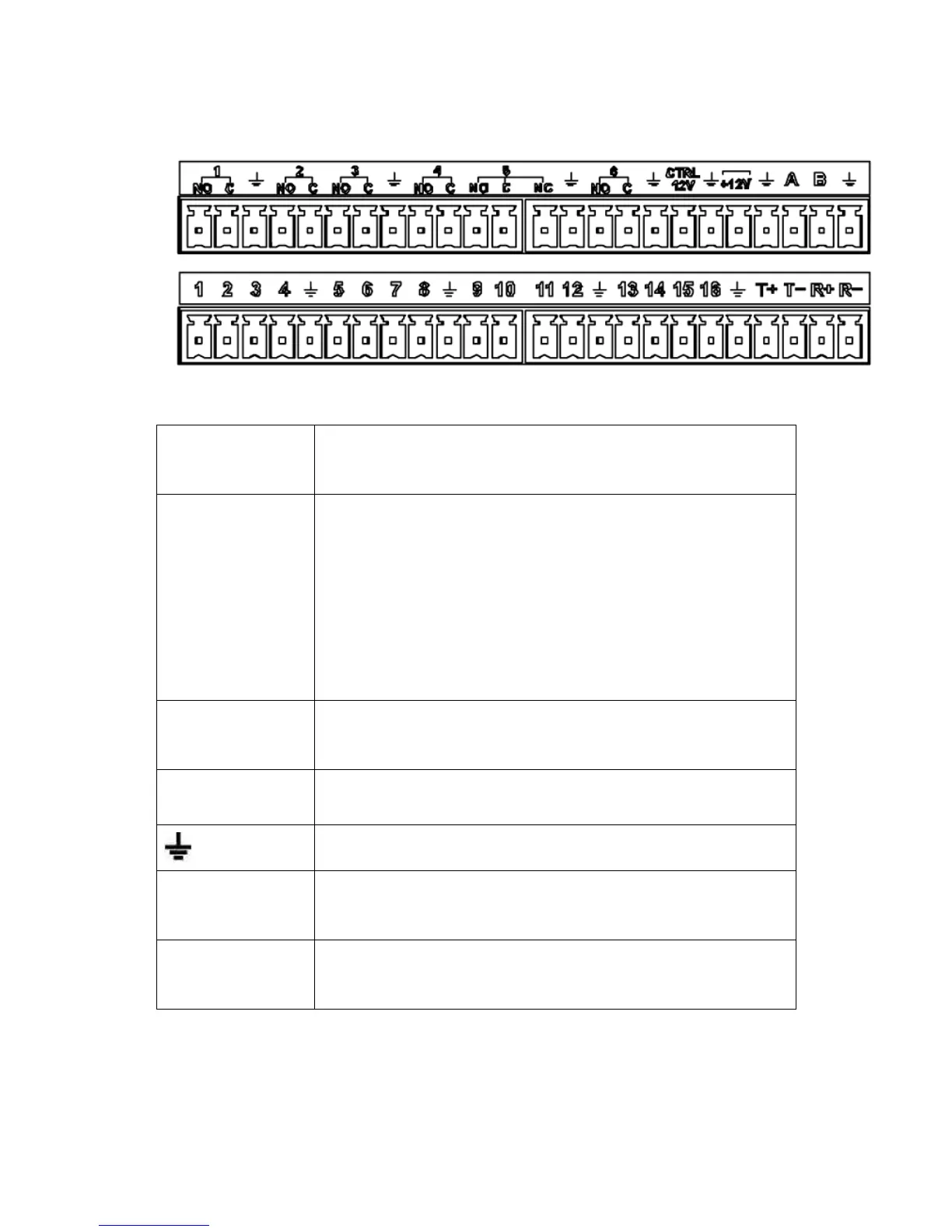
Figure 3-1
1,2,3,4,5,6,
7,8,9,10,11,
12,13,14,15,16
ALARM 1 to ALARM 16. The alarm becomes active in low voltage.
In the second line,
from the left to the
right:
NO1 C1,
NO2 C2,
NO3 C3,
NO4 C4,
NO5 C5,
NO6 C6.
There are six groups of normal open activation output (on/off button)
Control power output. For external alarm, you need to close the
device power to cancel the alarm.
Voltage current;500mA.
Rated current.
Voltage current;500mA.
485 communication port. They are used to control devices such as
decoder. 120Ω should be parallel connected between A, B lines if
there are too many PTZ decoders.
They are four-wire full-duplex RS485 port
T+ T-: output wire
R+ R-: input wire
3.7.2 Alarm Input Port
Please refer to the following sheet for more information.
Grounding alarm inputs. Normal open or Normal close type)