Technical Manual WIC1 SEG Electronics GmbH
DOK-TD-WIC1E, Rev. M 19
5. Technical Data, Characteristics and Features
5.1 Protective functions
5.1.1 Minimal operating current and rated primary current
In order to operate reliably, the WIC1 – as all CT-powered protection relays – needs a minimal current flowing con-
stantly in one of the phases. This minimal current is the smallest rated CT current (IS) x 0.9 listed in table.
The real rated current of the operating component to be protected is adjusted by parameter IS. All further settings
at the protection relay refer to the adjusted IS. This is to be described in the following example;
Boundary condition:
Setting IS = 40 A, CT type W3, 32 to 112 A
Setting I>: 1.1 x IS = 1.1 x 40 A = 44 A
Setting I>>: 10 x IS = 10 x 40 A = 400 A
Setting IE>: 0.2 x IS = 0.2 x 40 A = 8 A
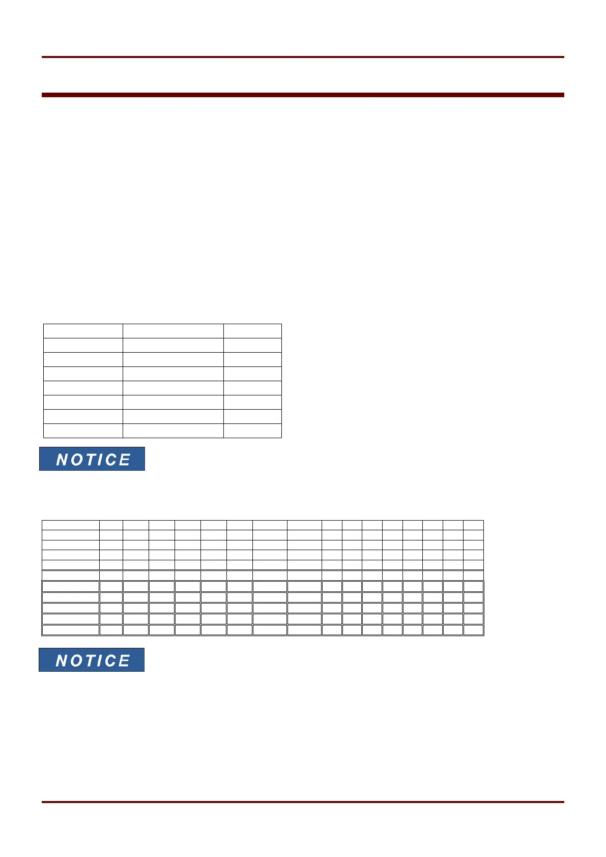
Depending on the CT type, an adjustment for relay version WIC1-1 is possible in the following scaling:
only for setting via serial interface
For relay versions WIC1-2 and WIC1-3 the following rated CT currents are adjustable either by DIP switches 1-4
(switch block 1) (Please note, DIP 4 is without function for the WIC1-2F) or HEX switch 1:
* All values are primary values in Ampere
Table 5.1
 Loading...