Technical Manual WIC1 SEG Electronics GmbH
DOK-TD-WIC1E, Rev. M 45
6.5 Selection of the secondary test system
When selecting the secondary test system the following particulars should be taken into account.
Secondary test system to be used as power source.
Three phases for the earth current test, one phase for the phase current test
(see chapter 6.7).
Sufficient output power for the switching points to be tested (see chapter 6.7.2 and 6.7.3).
The highest possible test current for testing via the test winding is at 22.4 A. A test
system with an output current up to 10 A should be enough.
A timer for measuring the time 0 – 300s. The time signal can be measured via the WIC1
outputs TC+/TC- or FI+/FI- as positive edge of a 24V signal.
6.6 Checks during commissioning
When putting into operation, the wiring and setting of the protection relay should be checked. Here the person do-
ing the commissioning work is assisted by the integrated test windings of the WIC1 protection system, which are on
the front of the relay. Hence any wiring jobs as well as actions in the cable connection area can be disregarded.
6.6.1 Wiring checks
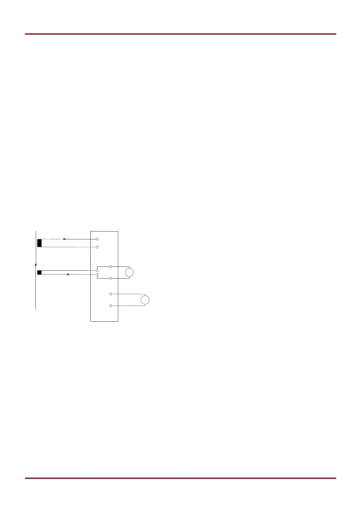
Wiring has to be checked with the circuitry shown in the diagram below.
Figure 6.3: Connection of a single-phase testing device (phase L1) with CT type WIC1W2AS1
The testing current is fed via sockets L1, L2, L3 and N. The test winding is rated such that the fed current of 1A
balances a primary current of 50A (CT type WIC1W2AS1). The timer should be connect parallel to the tripping coil
or the flag indicator. If there is no tripping coil or flag indicator available when the test is performed, an input resistor
should be connected to the timer. The resistance of a timer should be in the range of 20 up to1 k. This prevents
false measurements when tests are repeated in short intervals because the energy store cannot be discharged.
 Loading...