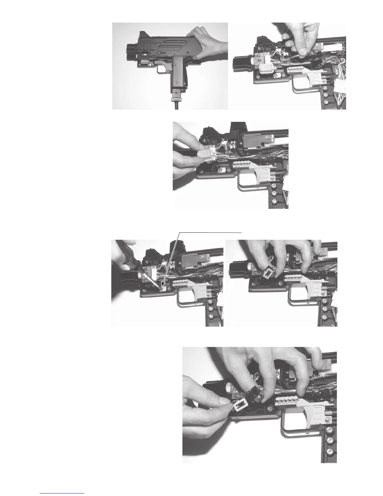
3) Place cover R face down on the work
surface and slowly lift cover L
directly upward.
4) Lift the trigger microswitch up from
where it is attached to cover R.
PHOTO 10b
PHOTO 10c
5) Remove the solder, allowing you to
remove the microswitch.
6) The grenade button microswitch is
located at the base of the grenade
button. Lift the grenade button free of
cover R.
7) Remove the screw and remove
microswitch cover R.
PHOTO 10d
PHOTO 10e
Screw (1), black
M3 x 6, w/spring washer
8) Undo the brackets and remove the solder to allow you to remove the
microswitch.
9) Solder the new microswitch in place on the gun. Then operate all buttons
on the gun and confi rm that the microswitch turns ON/OFF before
putting covers L and R back together.
Do not tighten the screws too tightly when reattaching the covers.
10) Perform an input test as described in the chapter on “Test Mode.”
PHOTO 10f
34
 Loading...