Do you have a question about the Sega Transformers Human Alliance and is the answer not in the manual?
Identifies and locates essential components included in the package for installation.
Step-by-step instructions for assembling the game machine components.
Specific instructions for installing the billboard lighting component.
Details on connecting the power supply and other electrical components safely.
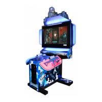
Explains the fundamental gameplay mechanics and objectives of the game.
Describes the function of the switch unit and coin meter for game operation.
Guides users on navigating and utilizing the game's test mode features.
Details how to view and access recorded game data and statistics.
Instructions for testing all input devices to ensure proper functionality.
Procedures for testing all output devices used within the game.
Configuration options for game difficulty, sound, and other settings.
Steps to calibrate controller crosshair positions for accurate gameplay.
Procedure to clear all recorded game data and records.
Instructions for repairing and maintaining the motor within the controller.
Guidance on troubleshooting and maintaining the infrared sensor in the controller handle.
Procedures for repairing and maintaining the mobile potentiometers in the controller.
Steps for repairing and maintaining the up/down mobile potentiometers.
Instructions for checking and repairing the LED panel in the controller.
Steps to disassemble the button plate to access the start button mechanism.
Procedure to detach the micro-switch from its housing.
Guidance on transferring wiring harnesses to a new micro-switch.
Instructions for repairing and maintaining the brake light panel components.
Maintenance procedures for the lamp components located on the sides of the plate.
Steps for maintaining the lamp situated on the control table.
Identifies the main components of the LCD display system.
Explains the purpose and operation of the control panel buttons.
Procedure for resolving coin jams in the coin selector mechanism.
Guidelines for cleaning and maintaining the coin selector for optimal function.
Steps for testing the coin insertion mechanism to ensure correct operation.
Instructions for replacing the lamp box and its lighting tube in the billboard.
Procedure for replacing the lamp panel assembly of the billboard.
Details on how to access the start button's switch and lamp by removing the plate.
Steps for removing the control panel's button plate for access.
Troubleshooting guide for unresponsive aim point movement when swinging controller left/right.
Troubleshooting guide for unresponsive aim point movement when swinging controller up/down.
Identifies the physical location of the RINGEDGE2 game board within the machine.
Procedures for cleaning the RINGEDGE2 board to prevent malfunctions.
Overview of the components and settings of the RINGEDGE2 board.
Explains common error codes and their solutions for the RINGEDGE2 system.
A diagram showing the overall assembly of the game machine with numbered parts.
Detailed breakdown of the mainframe components and their part numbers.
Lists the part numbers for the control board cover assemblies.
Identifies the part number for the left front cover of the controller stand.
Identifies the part number for the right front cover of the controller stand.
Lists part numbers for the 55-inch controller control plate assemblies.
Specifies the part number for the LCD wood shell enclosure.
Lists the part numbers associated with the LCD assemblies.
Identifies the part number for the left side billboard plate.
Identifies the part number for the right side billboard plate.
Lists the part numbers for the lighting box assemblies.
Specifies the part numbers for the controller assemblies.
Identifies the part number for the control board wood block.
Specifies the part number for the base box back gate.
Identifies the part number for the base box side gate.
| Type | Arcade Game Machine |
|---|---|
| Genre | Light Gun Shooter |
| Developer | Sega |
| Publisher | Sega |
| Players | 2 |
| Release Year | 2013 |
| Light Gun Shooter | Yes |
| Display | LCD |
| Based On | Transformers Film Series |
| Cabinet Type | Upright, Deluxe |
| Control Method | Light Gun |