Schweitzer Engineering Laboratories, Inc. SEL-2414 Data Sheet
3
I/O (Status and Alarms)
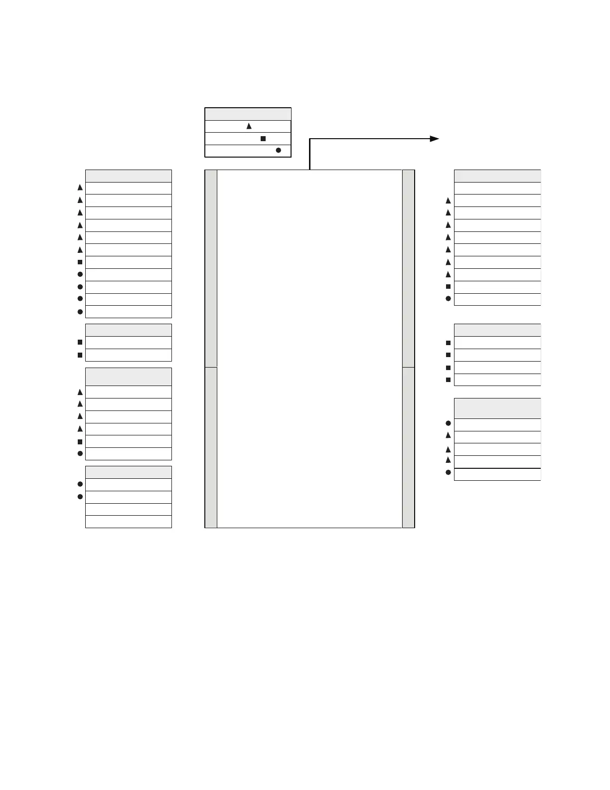
Use digital inputs to monitor critical alarms such as oil levels, pressures, and gas accumulation; they may also be used
for status points such as fans on/off and breakers open/closed, as shown in Figure 2.
Figure 2 Monitoring Inputs and Control Outputs
SEL-2414
Transformer Monitor
Digital Inputs (DIs) Analog Inputs (AIs)
Digital Outputs (DOs) Analog Outputs (AOs)
Sudden Pressure #
Low/High Oil Tank Level
Fan/Pump #1 On On/Off Fan Bank #1
On/Off Fan Bank #2
RTDs or TCs
(Temperature)
Ambient
Top-Oil (3 for 1)
Measured Hot-Spot
Bottom-Oil (3 for 1)
OLTC Low/High Oil Level
OLTC Tap Position
OLTC Remote/Local
Gas Accumulation #
# = Buchholz
SCADA Alarms
Sudden Pressure Alarm #
Low/High Oil Tank Level
Gas Accumulation Alarm #
Top-Oil Alarm
Hot-Spot Alarm
OLTC Oil Differential Alarm
Pressure/Vacuum Alarm
Pressure Relief Alarm
Cooling Alarm
Load Voltage (3 for 1)
Load Current (3 for 1)
OLTC Tank Oil
Sensors
Pressure/Vacuum Switch
Pressure Relief Device
Loss of Auxiliary Power
OLTC Control Mode
Sensors
Other Cooling . . .
OLTC Motor Current
Fan/Pump #2 On
Wire the digital outputs of sensors to the
digital inputs of the transformer monitor.
Wire digital outputs of the transformer monitor to digital inputs of
the SCADA system or to devices that need to be controlled.
Wire RTD/TC/Analog outputs of sensors to the
RTD/TC/Analog inputs of the transformer monitor.
ControlStatus
SCADA and/or Local HMI Communications
On/Off Fan Bank #3
On/Off Fan Bank #4
Fan Motor Running Timer
OLTC Tap Position
Core & Coil =
Key
Fan/Pump Bank =
On-Load Tap Changer =
General Alarm
Tap Position
Top Oil Temperature
Transduced
Quantities
Ambient Oil Temperature
Bottom Oil Temperature
LTC Tank Oil Temperature

 Loading...