Schweitzer Engineering Laboratories, Inc. SEL- 2664S Data Sheet
7
The following features of QuickSet monitor, commission,
and test the SEL-2664S.
➤ The PC interface remotely retrieves power system
data.
➤ The HMI monitors meter data, Relay Word bits,
and output contacts status during testing. The
control window allows resetting of diagnostics, and
targets.
➤ The Firmware Loader in the Tools menu helps you
upgrade the firmware.
Applications
The SEL-2664S is intended for high-resistance grounded
generator applications and cannot be used with low-
impedance-grounded, solidly grounded, and ungrounded
configurations. See Application Considerations in the
SEL-2664S Instruction Manual for additional details.
You can use the SEL-2664S to provide protection at
standstill and online with most typical levels of third-
harmonic voltage (VN3). The injection-based function of
the SEL-2664S requires that VN/NN terminal voltage
remains under 26 V peak. If a generator produces VN3
above this level, even under normal load conditions, the
injection signal stops, disabling the 64S elements.
However, 59N1, 59NRMS, and 64F elements continue to
protect the generator, and 64S elements are immediately
restored when VN3 drops below the safe level. Because
high VN3 indicates there is no ground fault near neutral,
the disabling of 64S elements has an insignificant impact
on protection.
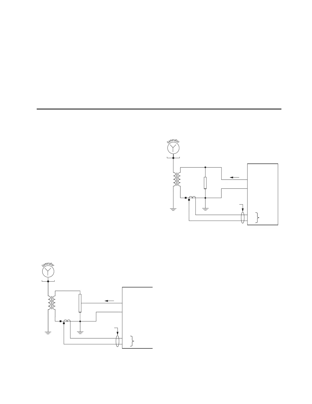
If you want to avoid disabling 64S elements, the
SEL-2664S can be configured to inject a signal at an
NGR Tap. See Figure 7 for basic ac connections using the
NGR Tap.
Figure 7 Basic AC Connections Using the NGR Tap
Figure 8 and Figure 9 show the ac connections for the
SEL-2664S with the neutral CT on the secondary side of
the neutral grounding transformer.
Figure 8 AC Connections With Neutral CT on the
Secondary Side of the Neutral Grounding Transformer
IN
TAP %
NGR
NGT
CTN
D02/VN
D01/NN
C02
C01
SEL-2664S
2-C Twisted Pair.
Do not ground the
CTN leads.
I_SRC
100%
X1 X2
IN
NGR
NGT
CTN
D02/VN
D01/NN
C02
C01
SEL-2664S
2-C Twisted Pair.
Do not ground the
CTN leads.
I_SRC
X1 X2



 To Next Page