3
10. Apply power supply voltage q to terminals A01+ and A02–, and reconnect the ground wire to the green
ground screw.
If you have a two-line display front panel, perform Step 11 through Step 19; if you have a touchscreen
display front panel, proceed to Step 20.
11. If the card is in the proper slot, the front panel displays the following:
STATUS FAIL
X Card Failure
If you do not see this message and the ENABLED LED is turned on, the card was inserted in the wrong slot.
Begin again at Step 2.
12. Press the ESC pushbutton.
13. Press the Down Arrow pushbutton until
STATUS is highlighted.
14. Press the ENT pushbutton.
The front panel displays the following:
STATUS
Relay Status
15. Press the ENT pushbutton.
The front panel displays the following:
Serial Num
000000000000000000000000
16. Press the ENT pushbutton.
The front panel displays the following:
Confirm Hardware
Config (Enter)
17. Press the ENT pushbutton.
The front panel displays the following:
Accept New Config?
No Yes
18. Select Ye s and press the ENT pushbutton.
The front panel displays the following:
Config Accepted.
Enter to Reboot
19. Press ENT and proceed to Step 22.
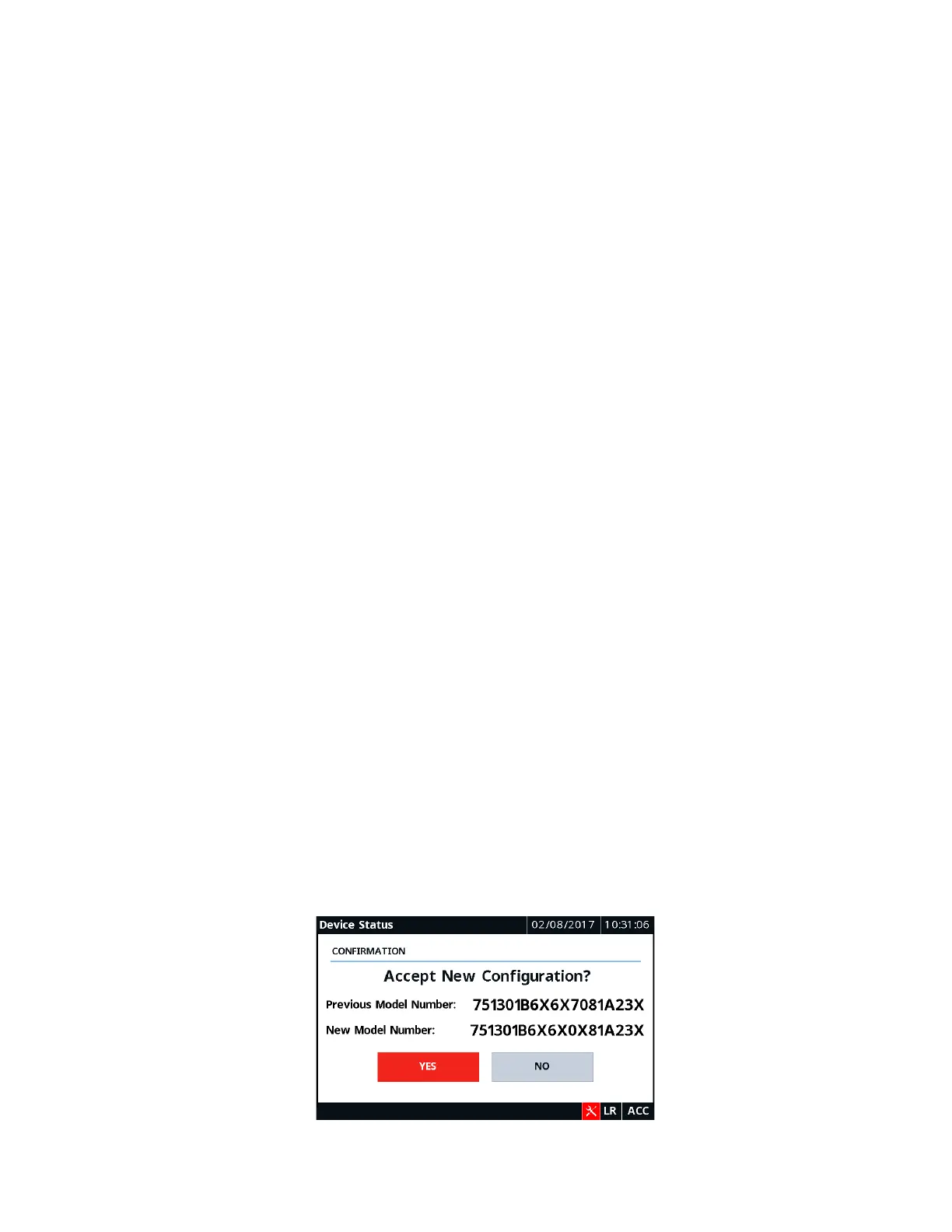
20. Wait for the Device Status screen to appear, and then verify the new part number and tap Ye s to confirm
the new configuration.
21. Tap OK on the notification screen to reboot the relay.