2
RX
TX
+
—
+
—
+
—
+
—
+
—
+
—
+
—
+
—
+
—
+
—
5 4 3 2 1
9 8 7 6
5 4 3 2 1
9 8 7 6
Port 4 DeviceNet
(Optional)
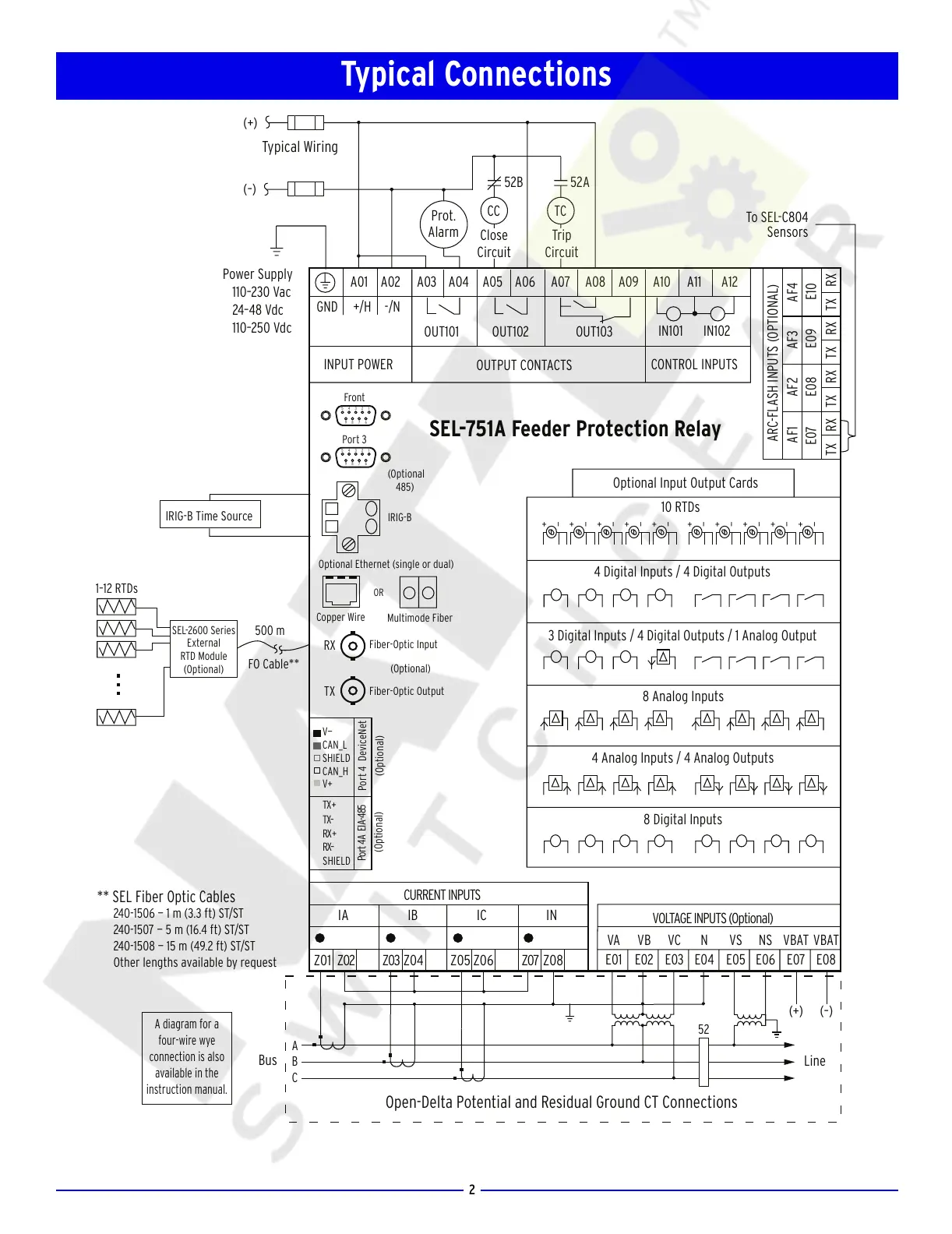
Open-Delta Potential and Residual Ground CT Connections
Typical Wiring
Prot.
Alarm
OUT101
OUT102
OUT103
A01 A02 A03 A04 A05 A06 A07 A08 A09 A10 A11 A12
IRIG-B
IA IB IC IN
Z07Z06Z05Z04Z03Z02Z01 Z08
TX+
TX–
RX +
RX–
SHIELD
(Optional)
Port 4A EIA-485
IRIG-B Time Source
500 m
FO Cable**
1–12 RTDs
Optional Input Output Cards
10 RTDs
4 Digital Inputs / 4 Digital Outputs
3 Digital Inputs / 4 Digital Outputs / 1 Analog Output
8 Analog Inputs
4 Analog Inputs / 4 Analog Outputs
Front
Port 3
TCCC
8 Digital Inputs
(+)
(–)
52B 52A
Close
Circuit
Trip
Circuit
IN101 IN102
CONTROL INPUTS
INPUT POWER
OUTPUT CONTACTS
SEL-751A Feeder Protection Relay
A diagram for a
four-wire wye
connection is also
available in the
instruction manual.
Power Supply
110–230 Vac
24–48 Vdc
110–250 Vdc
(Optional
485)
(Optional)
Fiber-Optic Input
Fiber-Optic Output
SEL-2600 Series
External
RTD Module
(Optional)
** SEL Fiber Optic Cables
240-1506 — 1 m (3.3 ft) ST/ST
240-1507 — 5 m (16.4 ft) ST/ST
240-1508 — 15 m (49.2 ft) ST/ST
Other lengths available by request
A
C
B
Line
52
Bus
Optional Ethernet (single or dual)
Copper Wire
OR
Multimode Fiber
(+) (–)
CURRENT INPUTS
VOLTAGE INPUTS (Optional)
TX RX TX RX TX RX TX RX
E07 E08 E09 E10
AF1 AF2 AF3 AF4
ARC-FLASH INPUTS (OPTIONAL)
To SEL-C804
Sensors
VA VB VC N VS NS VBAT VBAT
E01 E02 E03 E04 E05 E06 E07 E08
V—
CAN_L
SHIELD
CAN_H
V+
GND +/H -/N
Typical Connections
Courtesy of NationalSwitchgear.com