32
9.6) OUTPUT CURRENT CALIBRATION
MINIMUM CURRENT CALIBRATION
1) Set the generator to TIG LIFT mode.
2) Attach the ammeter clip to the negative cable.
3) Set the potentiometer on the front panel to the minimum value.
4) Begin to weld.
5) Calibrate, using trimmer P2 of the front panel board 15.14.246, the minimum welding current value to 5 + 1A.
MAXIMUM CURRENT CALIBRATION
1) Set the generator to TIG LIFT mode.
2) Attach the ammeter clip to the negative cable.
3) Set the potentiometer on the front panel to the maximum value.
4) Begin to weld.
5) Calibrate, using trimmer P1 of the front panel board 15.14.246, the maximum welding current value to 145 + 3A.
9.7) SHUNT CHECK
The current sensing is done by a shunt, i.e. a bar of very low resistance made of constantan alloy, through which the output current flows
and a voltage drop proportional to the output current is generated.
This voltage difference, of a few dozen mV, is proportional to the output current and is processed by the control logic present on board
15.14.243 to generate the reference signals for the power stage.
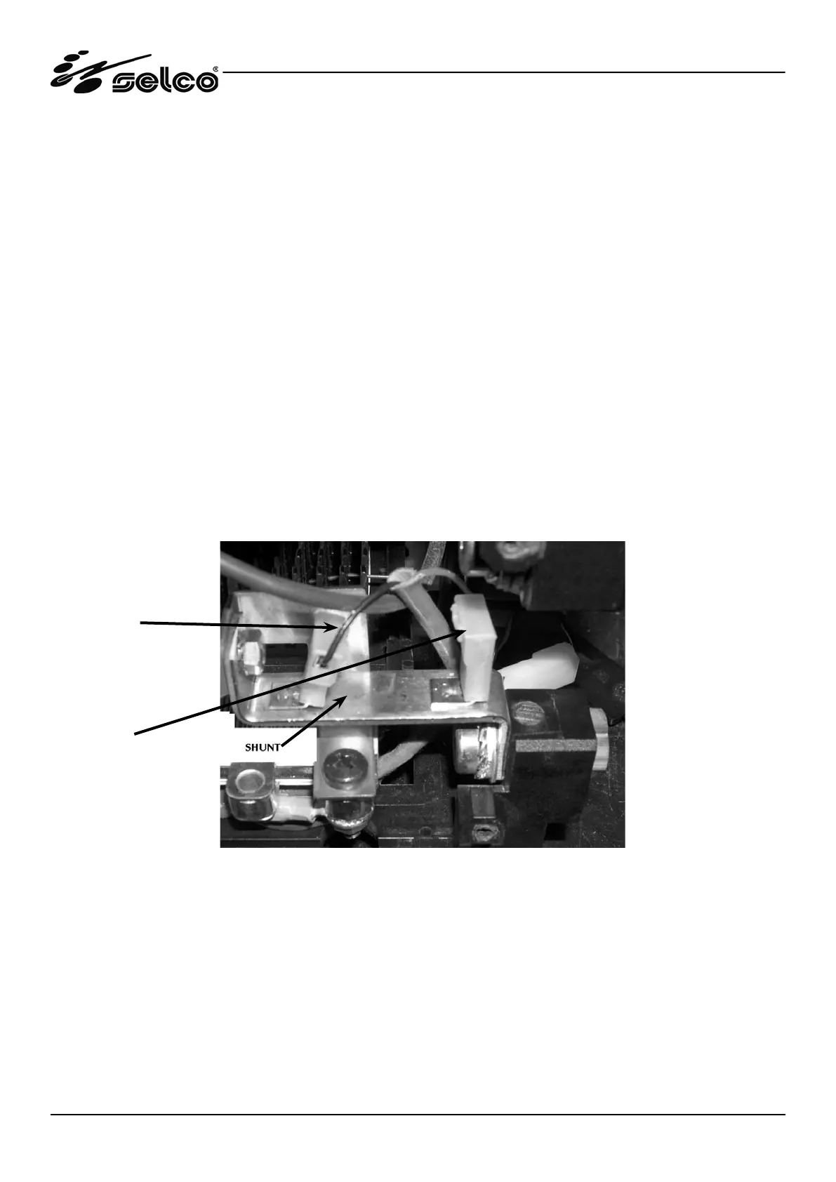
The shunt of the Genesis 145 generator is illustrated in the figure below.
Negative terminal of the SH-
shunt (Black wire)
Negative terminal of the SH+
shunt (Red wire)
SHUNT - View beneath the generator after removing the bottom
Ensure that the black wire and the red wire are properly connected and that the FASTON connectors are setting and tightening
in the correct position.