9
5) MACHINE DESCRIPTION
These constant current inverter power sources are able to perform
the following types of welding with excellent results:
- MMA,
- TIG (with reduction in the current on short-circuiting).
In inverter welders, the output current is unaffected by variations in
the supply voltage and the length of the arc, and is perfectly levelled,
giving the best welding quality.
The generator is equipped with:
- positive (+) and negative (-) socket,
- front panel,
- rear control panel.
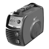
5.1) FRONT CONTROL PANEL (FIG.1)
* L1 : Voltage warning light green led.
Comes on with the start switch (Fig.2) “I1” in position “I” and indica-
tes that the plant is on and there is voltage.
* L2 : Safety device warning light yellow led.
lndicates that the safety devices like thermal cutout. With “L2” on,
the power source remains connected to the supply mains, but does
not supply output power. “L2” remains on until the fault has been
removed and in any case until the inner temperatures are not within
the normal values; in this case it is necessary to leave the power
source on to exploit the operating ventilator and reduce the time
when it is not active.
* P1: Potentiometer for setting the welding current
Allows you to continuously adjust the current both in TIG and in
MMA welding. This current stays unchanged when the supply and
welding conditions vary within the allowed ranges.
In MMA welding, the presence of HOT-START and ARC-FORCE
means that the average output current may be higher than that set.
* S1: MMA/TIG selection switch.
With the lever down: it is in electrode welding (MMA) mode, and
thus the HOT-START, ARC-FORCE and ANTI-STICKING are auto-
matically activated.
With the lever up: it is in the mode for welding with non-consu-
mable tungsten electrode in an inert atmosphere (TIG). The MMA
functions are removed, and the LIFT start is activated.
Fig. 1
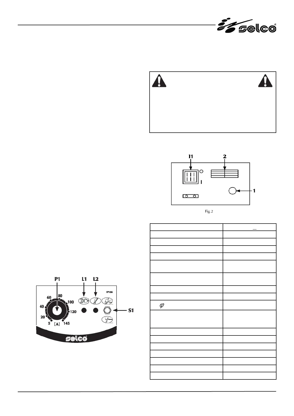
5.2) REAR CONTROL PANEL (FIG. 2)
* I1: Off/On switch
Turns on the electric power to the welder.
It has two positions, “O” off, and “I” on.
* 1 : Supply cable
* 2 : Ventilation slots. Never allow them to be obstructed.
5.3) TECHNICAL CHARACTERISTICS
Power supply voltage 50/60Hz 1x230Vac + 15%
Max. absorbed power (x=35%) 4.65kW
Max. absorbed current (x=35%) 31.1A
Absorbed current (x=100%) 18.6A
Absorbed current 2.50 (80A@40%) 9.2A
Absorbed current with
3.25 electrode (110 A @ 40%)
13A
Absorbed current with
4.00 electrode (140 A @ 40%)
17.8A
Efficiency (x=100%) 0.87
Power factor 0.7
Cos
0.99
Welding current (x=35%)
(x=60%)
(x=100%)
145A
120A
100A
Adjustment range 5-145A
Open-circuit voltage (limited) 62V
Protection rating IP23C
lnsulation class H
Construction standards EN60974-1/EN50199
Dimensions (lxdxh) 111x280x220 mm
Weight 4.1kg
Above data are referred to environment al 40°C
CAUTION
* With the I1 switch in the “I” on position, the welder is ope-
rational, and gives a voltage between the positive (+) and
negative (-) clamps.
* The welder is connected to the mains supply even if the I1
switch is in the “O” position, and therefore there are electri-
cally live parts inside it. Carefully follow the instructions gi-
ven in this manual..
 Loading...