IN0051 Revision 05 (005293)– 8 of 26
POWER PERFORMANCE PASSION
SP PRO Interactive Inverter Charger
Installing the blue or black Comm Card
1. Make sure that the SP PRO inverter is powered down. All Lights on the front panel will be off.
The three blue lights across the top will still be lit if there is AC source power (grid or generator).
This is Ok.
2. Remove the 4 Torx screws holding the original green comm card in the SP PRO.
Do not throw away the Torx screws, the screws will be used to remount the blue or black
Communication Card. (Mounting Screws)
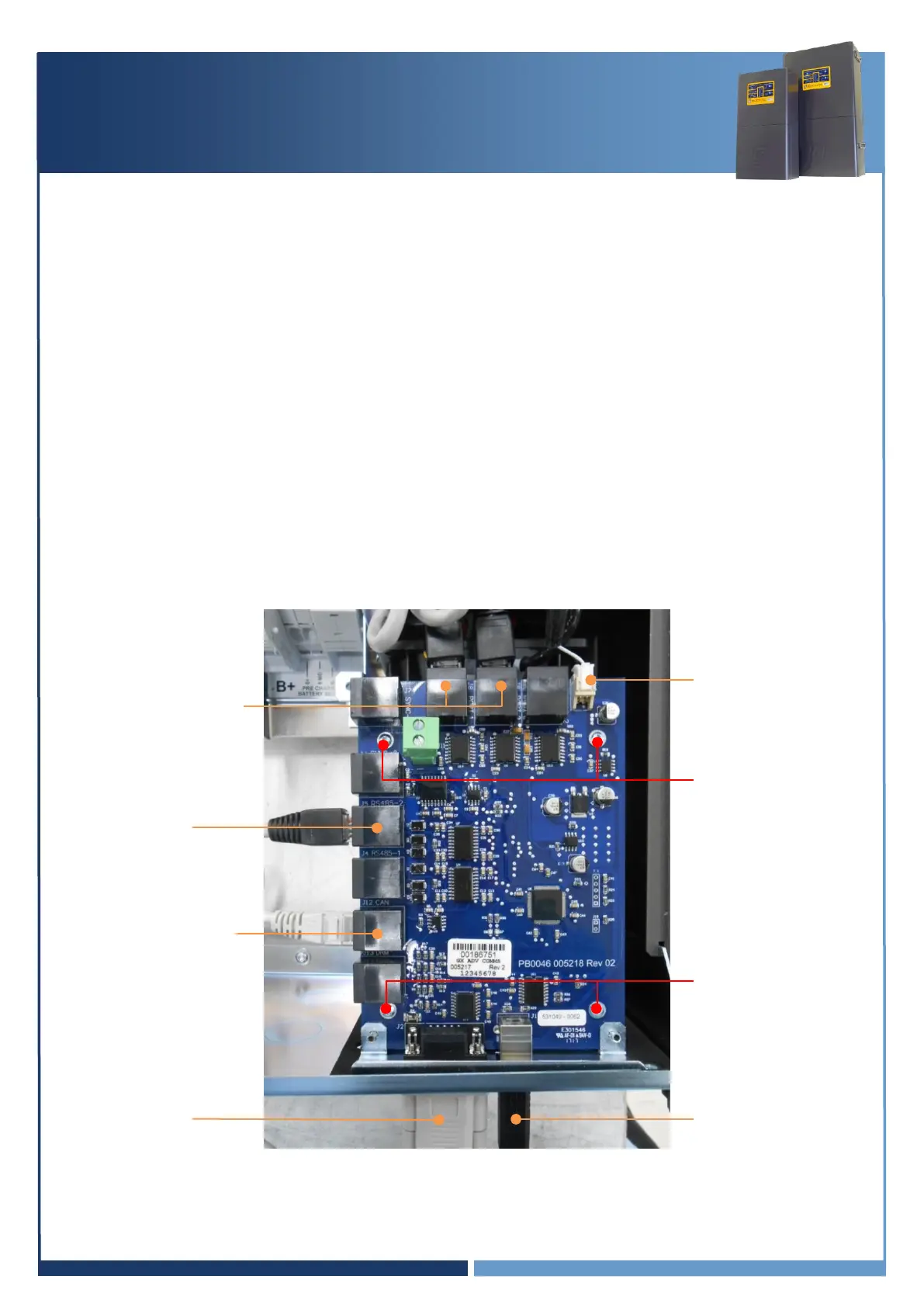
3. Remove the 2 short grey RJ45 connectors from the Control Board in the SP PRO. (Internal
Communications Ports 1 and 2)
4. Remove the white, 2 pin plug on the top right corner of the green comm card (Power)
5. Remove the original green comm card.
6. Connect the white, 2 pin plug to the top, right corner of the blue or black comm card. (Power)
7. Connect the two, small grey RJ45 leads to the blue or black comm card and into the Control
board in the SP PRO. (Internal Communications Ports 1 and 2)
8. Screw down the blue or black comm card into the SP PRO using the 4 Torx screws.
Internal Communications
Port 1 and 2
SCERT Comms to
Adaptor board
(J5 RS485-2)