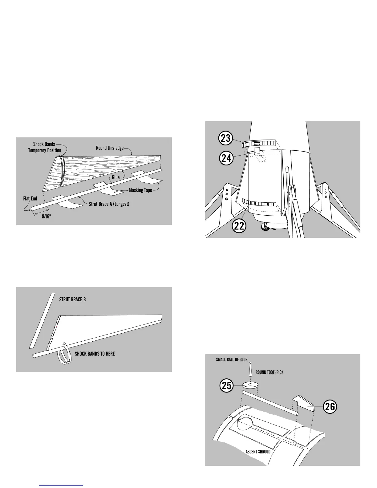
7. Pull the rubber bands around so they hang
freely from the brace as shown in the picture below.
Using the pieces left over from cutting the Strut
Brace A parts, cut 4 strut braces the same length as
pattern (B). Apply glue and attach as shown to the 4
struts.
8. Using the two 1/8” dowels you set aside,
earlier, cut 4 braces exactly the same as pattern (C).
Make sure that the diagonal cut on one end is
sharper than the one on the other. Roll a thin piece
of masking tape, cut 1/8” wide and 1-1/4” long
around the dowel 3/4” from the tapered end as
shown. Roll another piece of masking tape 2” from
the tapered end as shown. Slide one of the LL-2A
parts onto the strut brace as shown to make the
control cylinder and glue into place. Repeat this
procedure for the remaining three control cylinders.
6. Punch out the 4 balsa gear struts and round
one of the edges as shown. Loop two rubber bands
around the notch in each strut stretching them to
the top of the strut. Set two of the 1/8” dowels
aside for Strut Brace C later. All the dowels are not
the same diameter. There is one that is thinner. Set
it aside also. Cut four strut braces from the 1/8”
wood dowels exactly the same size as the pattern
supplied for brace (A) using a different dowel for
each piece. Apply glue to the longest edge of one
strut and then glue the strut brace to it leaving
9/16” of the end projecting from the rear of the as-
sembly as shown. Repeat this with the other three
struts.
55. Apply a coat of glue on the back side of
the rear descent stage body wrap and press it in
between two of the gear housings and even with
the rear of the descent body tube. Glue the other
three in the same manner. Then apply a coat of
glue to the four forward descent stage wraps. Ap-
ply them against the ascent module and in between
the gear housings. Apply glue to one side of a RCS
cover and glue as shown. Repeat for the other
three.
56. Cut two 2” lengths from the 1/12” dowel.
Apply glue 5/16” long from one dowel end. Center
an antenna disk over the glue and allow to set. Cut
two 5/16” lengths from each end of a wooden
toothpick. Glue the wide end of the toothpick to the
center of the antenna disk making sure it points
straight out. After the glue has dried, run a line of
glue along the backside of the antenna dowel and
glue it to the ascent module shroud. Make sure the
antenna points straight away from the module.
Then glue the antenna trim piece to the bottom of
the antenna.
 Loading...