54. Slide the engine nozzle shroud onto the
engine mount tube making sure that the engine
hook passes through the notches in the rings. Posi-
tion the large end of the nozzle even with the en-
gine tube end. Make sure that the engine hook
moves freely in the notches. Glue into place and
hold until it sets.
52. Next run a line of glue around the edge of
the ascent bulkhead and around the forward end of
the parachute tube. Slide on the command module
making sure the launch lug is through the notch
and glue into place. When the glue is dry cut away
the top of the launch lug at an angle so that it is
flush with the shroud.
53. Apply a thin line of glue around the large
end of the descent stage shroud. Pass the launch
lug through the bulkhead hole and glue into place
against the descent stage bulkhead. Be sure that it
is centered and hold until it sets. Trim the bottom of
the launch lug flush with the bulkhead.
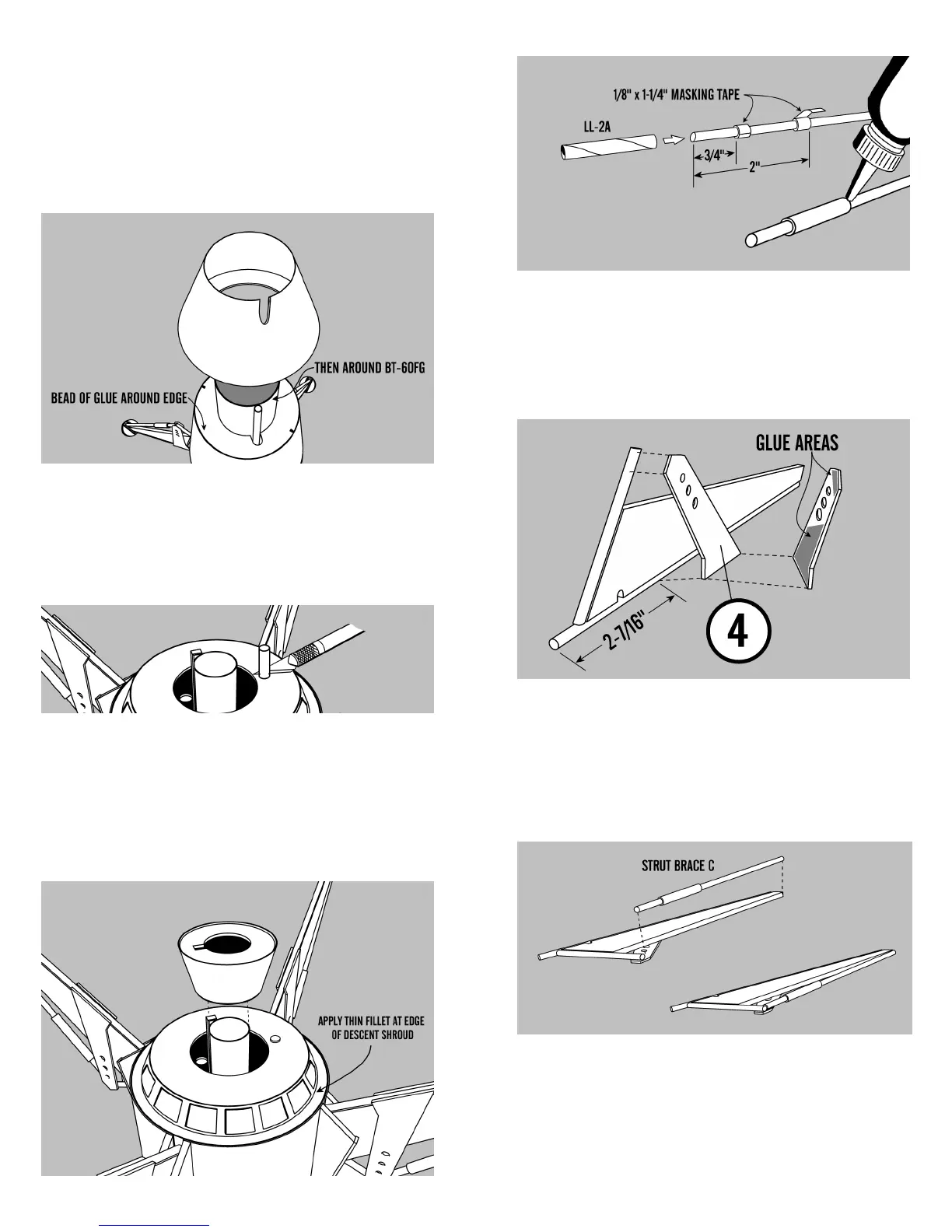
9. Mark each strut exactly 2- 7/16” from the
protruding end. Take one gear strut support and
glue it into position as shown against the landing
gear. Hold into place until the glue sets. Do the
same with the other three landing gears.
10. Apply glue to the gear support as shown
in the illustration below. Glue the strut brace on
with the control cylinder closest to the strut sup-
port. Be sure to glue the assembly exactly as
shown below and repeat for the other 3 assemblies.
11 . Glue the other gear support on to the as-
sembly exactly as you did the first one and hold in
place with masking tape until it sets. Repeat on the
other 3 assemblies.