EB-GS2971
Evaluation Board User Guide
52169 - 2 June 2012
5 of 22
Proprietary & Confidential
1.1 Power
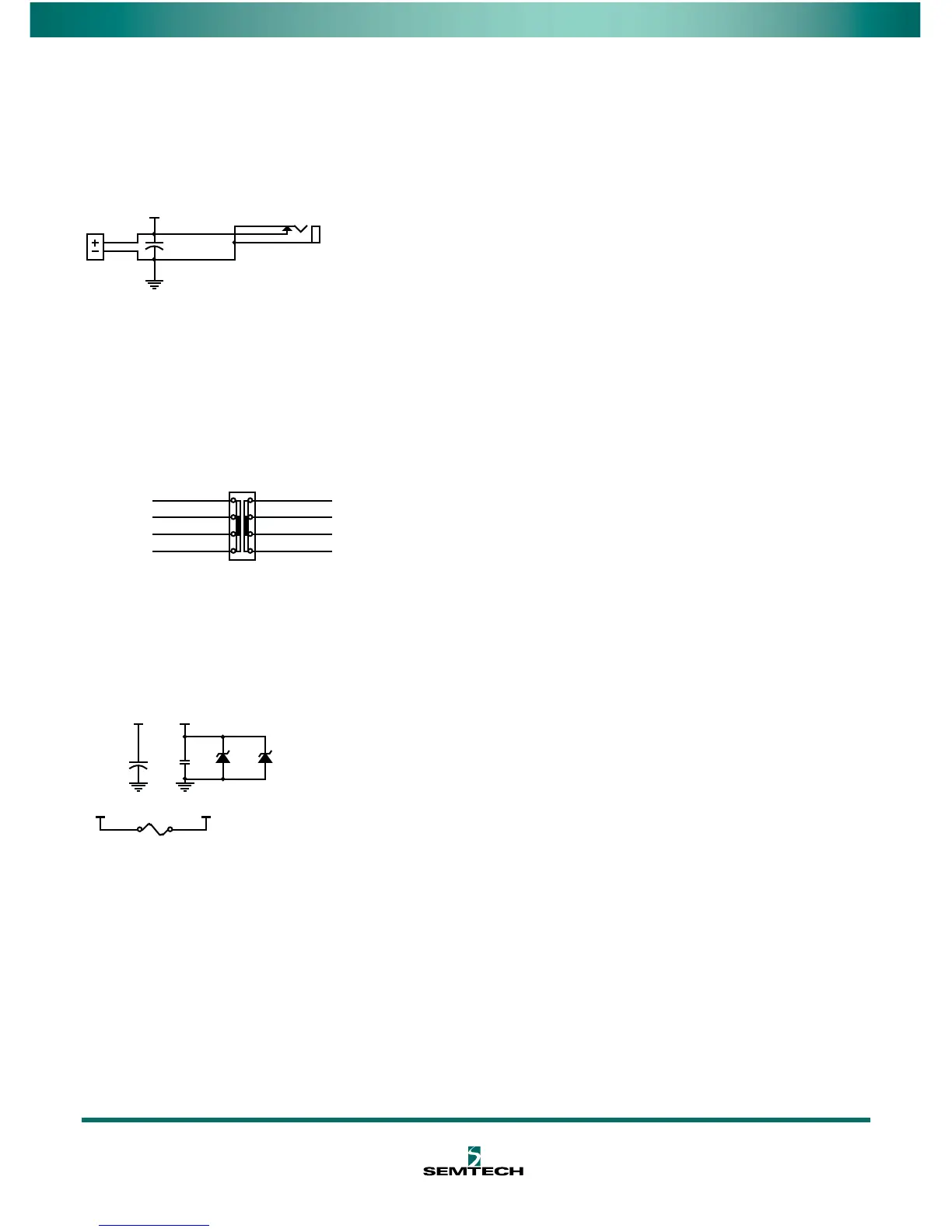
The EB-GS2971 requires a single +5V DC power supply. The board can be powered
through either J24 or J100. Additionally, the board can powered through J18 from an
EB-GS2972 or FPGA board.
Figure 1-2: Power Supply
Switch SW100 allows the user to select three different voltages: 5V Ext, 5V EB and 3.3V
FPGA. It is important to note that if you are interfacing with an FPGA, you must select
3.3V FPGA.
NOTE 1: If you have accidently selected 3.3V FPGA and connect to a EB-GS2972
Serializer board, protection* will turn on.
Figure 1-3: Power Selection Switch
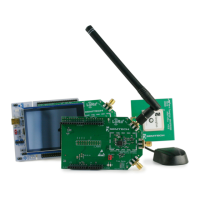
*The EB-GS2971 has features to protect the GS2971. A fuse (F101) will trip when the
Zener Diodes (D100, D101) turn on.
NOTE 2: If the fuse trips, it will recover in approximately 1 hour, with a resistance of 1Ω.
Figure 1-4: Power Protection
LED (D11) indicates the power on/off state of the board.
Through the use of jumper JP7, the GS2971 I/O voltage can be selected as either 1.8V or
3.3V.
If the EB-GS2971 and the EB-GS2972 are connected together, one supply will power
both boards. Therefore, the +5V DC power is only required on either the EB-GS2971 or
the EB-GS2972.
5V
J24
5V Input
GND
VCC_5V_In
3
2
1
J100
PJ-202AH
C36
EEV-FK1C221XP
5V
1
2
3
4
5
6
7
8
SW100
SW SLIDE-DP3T
VCC_3.3V
VCC_3.3V_reg
VCC_3.3V
VCC_MB_F
VCC_5V_In
VCC_5V
VCC_MB
VCC_LED
5V Ext
5V EB
3.3V FPGA
GND
D101
3.6V
VCC_MB
D100
3.6V
VCC_3.3V
F101
0603L035
C102
470u
VCC_MB VCC_MB_F
GND
C103
22u